Unoffical empeg BBS

Quick Links: Empeg FAQ | RioCar.Org | Hijack | BigDisk Builder | jEmplode | emphatic
Repairs: Repairs

Topic Options
#244427 - 20/12/2004 18:44 Bed-of-nails
mdavey
enthusiast

Registered: 06/03/2003
Posts: 269
Loc: Wellingborough, UK
A question for the hardware engineers.

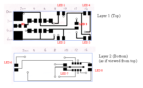
I have a design for a tiny PCB 6mm x 16mm, with a Microchip PIC microcontroller on it.

I would like to program the chip in-place and was thinking of using a cheap bed-of-nails setup, something like this:

http://img-europe.electrocomponents.com/largeimages/W434324-01.jpg

However, this particular item needs a custom-made jig AND doesn't provide any way to holde the piece in the jig as far as I can tell. I could just use three probes and hold them in-place during the programming, but that seems a bit hit-and-miss, mechanically.

The design has components on all edges and they can't be moved, so an edge connector is out of the question. Also, a header is out of the question for cost reasons. Because the circuit is at the design stage, the pads can be placed pretty much anywhere except at the edges of the board.

Does anyone know of a solution that:
* is really inexpensive
* would be quick to set-up
* will hold the piece in place (remember the small size)
_________________________
Michael
Ex-owner of stolen empeg #030102741

Top
#244428 - 20/12/2004 18:52 Re: Bed-of-nails [Re: mdavey]
schofiel
carpal tunnel

Registered: 25/06/1999
Posts: 2993
Loc: Wareham, Dorset, UK
Can you photograph the piece and post it here?
_________________________
One of the few remaining Mk1 owners... #00015

Top
#244429 - 20/12/2004 19:18 Re: Bed-of-nails [Re: mdavey]
mlord
carpal tunnel

Registered: 29/08/2000
Posts: 14478
Loc: Canada
Solder three lengths of wire to the pads, and put a connector on the end of them.

Top
#244430 - 22/12/2004 11:31 Re: Bed-of-nails [Re: mdavey]
Shonky
pooh-bah

Registered: 12/01/2002
Posts: 2009
Loc: Brisbane, Australia
6mm x 16mm can't be standalone so there must be some sort of connector off the board to other circuits. Can 3 pins be added to the connector? i.e. basically what Mark has said.

Beds of nails really need locating holes too. If you have enough space for the holes, that's the way.

If cost is so sensitive that a small connector is unfeasible, then I'm assuming high volume. High volume would exclude soldering wires to the board.

From the sort of vague description it would appear a bed of nails is the only option, possibly with a guide outside the board if no space for guid holes is available.
_________________________
Christian
#40104192 120Gb (no longer in my E36 M3, won't fit the E46 M3)

Top
#244431 - 22/12/2004 20:35 Re: Bed-of-nails [Re: Shonky]
mdavey
enthusiast

Registered: 06/03/2003
Posts: 269
Loc: Wellingborough, UK
Quote:
6mm x 16mm can't be standalone so there must be some sort of connector off the board to other circuits.


No connector, just 2-wire power to pads.

Quote:
Beds of nails really need locating holes too. If you have enough space for the holes, that's the way.

If cost is so sensitive that a small connector is unfeasible, then I'm assuming high volume. High volume would exclude soldering wires to the board.


High enough that I don't want to be soldering, unsoldering and cleaning up.

Here is the pre-CAD design, to give you a little more idea. There is a 6-pin SOT23 on layer one, with a pad on each of the outside legs - intended to be for a bed of nails setup.

A reminder of the question: Does anyone know of a (probably bed-of-nails) solution that (would allow me to program the chip in-place and):
* is really inexpensive
* would be quick to set-up
* will hold the piece in place (remember the small size)

[attachment]


Attachments
243980-all_rtf_m3c43572e.png (169 downloads)

_________________________
Michael
Ex-owner of stolen empeg #030102741

Top
#244432 - 22/12/2004 21:54 Re: Bed-of-nails [Re: mdavey]
Shonky
pooh-bah

Registered: 12/01/2002
Posts: 2009
Loc: Brisbane, Australia
You say there's no room for a connector on the edge but the track going to LED8 could easily be moved and you could have the pads on the side of the board. It doesn't appear the track layout will have any impact.

I'd just have 3 0.1" spaced pads on layer 2 ala an old PC ISA card and then make a 3 way connector to "plug" the boards into for programming.

Or have the boards already been made? If so, none of that helps
_________________________
Christian
#40104192 120Gb (no longer in my E36 M3, won't fit the E46 M3)

Top
#244433 - 22/12/2004 22:18 Re: Bed-of-nails [Re: Shonky]
mdavey
enthusiast

Registered: 06/03/2003
Posts: 269
Loc: Wellingborough, UK
Quote:
the track going to LED8 could easily be moved


But there are components on (at least) one side of each edge. The LEDs themselves can't be moved but the tracks could be re-routed.

Perhaps it the connector was short enough? Hmm.

Edit: No, I don't think a connector will work. The drawing isn't quite to scale (I did say it was pre-CAD) - that PIC gets pretty close to the edge. I also need the ability to reprogram the device, so part-populating the board then flashing the device isn't going to be a solution.


Edited by mdavey (22/12/2004 22:22)
_________________________
Michael
Ex-owner of stolen empeg #030102741

Top
#244434 - 22/12/2004 22:29 Re: Bed-of-nails [Re: mdavey]
Shonky
pooh-bah

Registered: 12/01/2002
Posts: 2009
Loc: Brisbane, Australia
I'm assuming every component is visible. Only half of the board needs to go in the connector. The end with the LEDs could just hang out.
_________________________
Christian
#40104192 120Gb (no longer in my E36 M3, won't fit the E46 M3)

Top
#244435 - 23/12/2004 06:25 Re: Bed-of-nails [Re: mdavey]
genixia
Carpal Tunnel

Registered: 08/02/2002
Posts: 3411
It's either a custom jig or a custom probe. If your pcb size is consistent then a custom jig shouldn't be too hard to make, just fiddly. Find some acetal or similar and carve away. I'd suggest a cheap chopping block as a source of suitable plastic. Cut a base plate, drill for your pins, insert and glue. Build up an outer perimeter until you get to the level of your pcb. I'd suggest that the final layer (at pcb level) consists of 2 U-shaped pieces to make removal of the pcbs easier. Glue the whole lot together.

You could probably secure the pcbs within the fixture with nothing more than a rubber band wrapped around the whole thing. A couple of grooves in the top 'U's will help locate this band.

I've whacked together a quick CAD model using 3 layers of 10mm thick acetal, assuming that the pins are 2mm tapering to .2mm thick and 25mm long. Each pad in this model has a plated through hole (0.5mm). That should help with the registration, allowing you to ease up on the tolerance of the pcb outline.

Unfortunately I had to screenshot the images so they are in that nasty Word .doc format, rather than a bunch of nice jpegs. But hopefully it should give you an understanding of what I mean. Get your dremel out!

The only alternative that I can see is to make a single probe containing all the pins. This would be much easier to man handle than multiple probes. Use a stock pin header as the probe head - this gives you a predetermined pitch for your pads which allows you to put some registration holes in. (Make sure they are slightly smaller than the pin diameter obviously.)

bedofnails.doc
_________________________
Mk2a 60GB Blue. Serial 030102962 sig.mp3: File Format not Valid.

Top
#244436 - 23/12/2004 06:26 Re: Bed-of-nails [Re: genixia]
genixia
Carpal Tunnel

Registered: 08/02/2002
Posts: 3411
BTW, not sure if you need one or not, but you don't appear to have any decoupling caps.
_________________________
Mk2a 60GB Blue. Serial 030102962 sig.mp3: File Format not Valid.

Top
#244437 - 01/01/2005 15:26 Re: Bed-of-nails [Re: mdavey]
mdavey
enthusiast

Registered: 06/03/2003
Posts: 269
Loc: Wellingborough, UK
Thanks to everyone that posted suggestions.

I liked Shonky's connector idea but couldn't see a way to get it to work with my design that has components alone every edge. I'm probably going to go with genixia's chopping board suggestion and use the Farnell probes I posted at the top of this thread. I have a Dremel, so it should be fun making a little jig. Plus, a chopping board will give me enough material to make a few attempts if the drill wanders and I don't get the holes for the probes just right first time.

I did think about using an old smart-card connector (the sort you find under the battery in mobile 'phones), so that might be my backup plan.

I'll let you know how I get on. Thanks again.
_________________________
Michael
Ex-owner of stolen empeg #030102741

Top