#308108 - 12/03/2008 18:42
 Electronics help- H-Bridge is annoying me
|
old hand
Registered: 09/01/2002
Posts: 702
Loc: Tacoma,WA
|
I am working on a project where I need a DC motor to run forwards and backwards. After some research I thought that this H-Bridge would do the trick. So I hooked it up via an Arduino (AVR chip) to provide logic control and a wall-wart (3A) 12VDC supply to provide power for the motor. The motor runs and stops as instructed by the AVR, but no matter what it always runs in the same direction even though the AVR chip should be telling it to run in two directions. Can any electronics experts here tell me why this @#$@# motor would only run in one direction connected to this H-Bridge? The schematic is attached for those so inclined. I'm attaching the motor to the H Bridge by hooking up output 1 of the bridge to one motor pole and output 2 to the other motor pole (is this right??).  Description: H Bridge Circuit with TLE5205 and Arduino Description: H Bridge Circuit with TLE5205 and Arduino
Edited by siberia37 (12/03/2008 18:48)
|
|
Top
|
|
|
|
|
#308109 - 12/03/2008 19:25
Re: Electronics help- H-Bridge is annoying me
[Re: siberia37]
|
addict
Registered: 11/11/2001
Posts: 552
Loc: Houston, TX
|
Have you tested the motor by connecting the power supply you've got directly up to the motor both ways to see if it can run in the other direction?
_________________________
--Ben
78GB MkIIa, Dead tuner.
|
|
Top
|
|
|
|
|
#308110 - 12/03/2008 19:25
Re: Electronics help- H-Bridge is annoying me
[Re: siberia37]
|
carpal tunnel

Registered: 29/08/2000
Posts: 14478
Loc: Canada
|
I have a similar project underway here right this minute!. This L293D driver chip is what I'm using, wired in a circuit like this simple kit uses (page 10).
Edited by mlord (12/03/2008 19:34)
|
|
Top
|
|
|
|
|
#308111 - 12/03/2008 19:33
Re: Electronics help- H-Bridge is annoying me
[Re: siberia37]
|
carpal tunnel
Registered: 29/08/2000
Posts: 14478
Loc: Canada
|
Your wiring looks correct, but the datasheet shows an unusual truth table on pages 4 and 5.
It looks like your two GPIO pins need to be 00 for one direction, and 01 for the other direction. Use 10 for "brake" mode, and 11 for "coast".
Cheers
Edited by mlord (12/03/2008 19:36)
|
|
Top
|
|
|
|
|
#308112 - 12/03/2008 19:48
Re: Electronics help- H-Bridge is annoying me
[Re: BAKup]
|
old hand
Registered: 09/01/2002
Posts: 702
Loc: Tacoma,WA
|
Yes the motor will run both directions on it's own.
|
|
Top
|
|
|
|
|
#308113 - 12/03/2008 19:56
Re: Electronics help- H-Bridge is annoying me
[Re: mlord]
|
old hand
Registered: 09/01/2002
Posts: 702
Loc: Tacoma,WA
|
Your wiring looks correct, but the datasheet shows an unusual truth table on pages 4 and 5.
It looks like your two GPIO pins need to be 00 for one direction, and 01 for the other direction. Use 10 for "brake" mode, and 11 for "coast".
Cheers Thanks- I will double check my coding on the AVR. If I still can't get it to work then I guess I will order some L293s. I'm not happy the L293 only outputs 600ma though. My motor will probably draw more than that.
Edited by siberia37 (12/03/2008 19:56)
|
|
Top
|
|
|
|
|
#308114 - 12/03/2008 20:16
Re: Electronics help- H-Bridge is annoying me
[Re: siberia37]
|
carpal tunnel
Registered: 29/08/2000
Posts: 14478
Loc: Canada
|
Your wiring looks correct, but the datasheet shows an unusual truth table on pages 4 and 5.
It looks like your two GPIO pins need to be 00 for one direction, and 01 for the other direction. Use 10 for "brake" mode, and 11 for "coast".
Cheers Thanks- I will double check my coding on the AVR. If I still can't get it to work then I guess I will order some L293s. I'm not happy the L293 only outputs 600ma though. My motor will probably draw more than that. You should be able to get it working with the chip you have -- probably just logic issues, which you can verify with a volt meter on the GPIO outputs. But if not, then each L293 D (you definitely want the D version, with built-in diodes, not the one without the D) has *two* complete H-bridges, which can be ganged up for 1.2Amp peak drive capability (as done in the sample board circuit I'm using here). Cheers
Edited by mlord (12/03/2008 20:18)
|
|
Top
|
|
|
|
|
#308115 - 12/03/2008 22:07
Re: Electronics help- H-Bridge is annoying me
[Re: mlord]
|
addict
Registered: 24/07/2002
Posts: 618
Loc: South London
|
AVR...shudders... 
|
|
Top
|
|
|
|
|
#308116 - 12/03/2008 22:32
Re: Electronics help- H-Bridge is annoying me
[Re: mlord]
|
old hand
Registered: 09/01/2002
Posts: 702
Loc: Tacoma,WA
|
Ok it ended up being some sort of logic error as suspected. The digital pin I was plugging in to must have had 2V logic because that was what was reading on the multimeter. I changed it to a different digital pin and it works fine now. Never knew the AVR had so many different logic levels...
|
|
Top
|
|
|
|
|
#308117 - 12/03/2008 22:58
Re: Electronics help- H-Bridge is annoying me
[Re: siberia37]
|
carpal tunnel
Registered: 24/12/2001
Posts: 5528
|
Ok it ended up being some sort of logic error as suspected. The digital pin I was plugging in to must have had 2V logic because that was what was reading on the multimeter. I changed it to a different digital pin and it works fine now. Never knew the AVR had so many different logic levels... Have you configured port D or any of the pins in there differently? It should do 5V.
|
|
Top
|
|
|
|
|
#308118 - 12/03/2008 23:00
Re: Electronics help- H-Bridge is annoying me
[Re: sn00p]
|
enthusiast
Registered: 21/02/2006
Posts: 325
|
Hi,
I noticed that your circuit only had high frequency decoupling (the 100nF), which is good, but there should be bulk low frequency decoupling as well. Maybe you already have it and it's not shown.
You will notice that in the LTE-5202 datasheet, they have a large decoupling capacitor (100uF to 4700uF) on the power pin.
MOSFETs are very good at instantaneously sucking energy from the supply to drive the load. The instantaneous power delivered to the chip is limited by the power supply source impedance and the inductance of the power interconnect to the Motor Driver Chip.
The bulk low frequency capacitor acts as a "local battery", much like a large capacitor (1 Farad or more), is located near a car power amplifier to reduce the "local" source impedance that the amplifier sees. It improves the local storage for the amplifier to improve low bass performance. The midbass and high frequency energy source impedance is supplied by the decoupling within the power amplifier.
The load in your case is composed of FET RDS(on) in series with the motor DC resistance. The time frame is governed by the FET edge rate, motor inductance, and interconnect.
The capacitor will also improve the initial torque of the motor as the voltage on the FETs remains closer to the applied voltage during the transient. The FET Bridge voltage droops when the motor is started or moved from a position where it draws higher peak currents. The capacitor keeps that voltage closer (more available current) to the rail voltage over the transient time. If capacitor is not there, the FETs will be starved for energy during that timeframe.
The capacitor could improve stability & reliability too.
Ross
_________________________
In SI, a little termination and attention to layout goes a long way. In EMC, without SI, you'll spend 80% of the effort on the last 3dB.
|
|
Top
|
|
|
|
|
#308124 - 13/03/2008 00:55
Re: Electronics help- H-Bridge is annoying me
[Re: Ross Wellington]
|
carpal tunnel
Registered: 29/08/2000
Posts: 14478
Loc: Canada
|
Regarding motor control circuits.. I've been having my own, different, issues here. I'm using a FT232RL USB breakout board to interface to the H-bridge circuits, all controlled from my MythTV box (for Frankenswitch V2). The problem I see, is that when the motor is under high load (aka. "stalled"), sometimes the FT232R disconnects/reconnects on the USB side, and consequently gets reset by the host. The host is using Linux (of course), and I looked into the low level code there. It's simply the UHCI hardware reporting a "connection change" event, meaning a disconnect/reconnect. So I figured maybe a voltage brownout on the USB cable was the cause, and then went through a progressive series of increasing the circuit isolation. Now the FT232R breakout board is still bus-powered, but simply connects to some opto-isolators, using internal (5V) drivers through 10K resistors to the O-I to ground. The motor controller side of the house is now triggered from the far side of the O-I, and runs on a totally independent PSU, all the way to the 120VAC wall outlet. Not even a ground wire is shared. The USB now behaves much better, but I can still cause it to disconnect/reconnect with repeated stressing of the motor. Why? The obvious guess here, for me anyway, is EMI from the motor, since I'm doing these tests with 6" or less physical distance between the motor and the FT232R. I suppose a nice grounded metal/foil shield, or simply more distance, should cure this. Or is there something better (yet easy) to also try? EDIT: Information on the FT232R Breakout Board is here. I have tied pin VccIO to Vcc. Cheers
Edited by mlord (13/03/2008 01:19)
|
|
Top
|
|
|
|
|
#308130 - 13/03/2008 05:27
Re: Electronics help- H-Bridge is annoying me
[Re: mlord]
|
enthusiast
Registered: 21/02/2006
Posts: 325
|
Hi,
EMI or EMC work like this is usually performed in an RF tight Chamber or certified open-field test sites, with calibrated antennas, and receivers or spectrum analyzers.
You are in the mode of identifying what the emission source(s) are first. It is either coming from the controller electronics, edge rate of the MOSFETs in the motor driver or from the motor.
The antenna for the emissions is the cable between the motor and the controller board including the traces on the controller board if they are surface routes. The USB cable could also be an antenna if it is not grounded well on both sides. Both sides need to grounded if the frequency exceeds 1 MHz or edge rates are faster than 1 us.
1.0 Servo Noise sources
-----------------------
You need to see if the noise is related to the controller electronics, Motor Driver, or the Motor.
1.1 Controller Noise Sources.
.............................
The controller will have a crystal controlled clock source on it near the processor chip. It divides this clock down and uses it for logic timing for the controller. The clock is used to create synchronous and asynchronous strobes, USB interface timing, and time databuss transaction. The noise will be heard as a whine for steady state clocks, clicks and chirps for strobes and buss transactions.
Note the oscillator frequency that is marked on it (like 4 MHz, 16 MHz, etc, it may be 3.579, 4.000 or 4000k). Multiply that frequency by 2, 3, 4, 5, 6, 7, 8, 9, and write the numbers down. Then divide the clock by 2 and multiply that number by 3, 4, 5, 6, 7, 8, 9, and write those down too. They will be suspect frequencies to look for as controller noise sources.
1.2 Motor Driver Noise Sources.
...............................
The Motor Driver usually makes noise based on the modulation frequency (5 khz to 20 kHz) or the edge rate of the MOSFETs (MHz). The modulation frequency will often be heard as a whine or gated buzz. The MOSFETs will generally be heard on the FM Radio and are usually pulsating white noise.
1.3 Common Motor Noise Sources.
...............................
Generally, the commutation of a common DC motor will generate predominantly broadband low frequency noise (hence, the AM radio for the receiver system) and also recessive high frequency noise from the commutation arcing.
1.4 Brushless DC Motor Noise Sources
.....................................
If it is a Brushless DC Motor, BLDC motors have noise in the higher frequency bands as the motor package re-radiate the conducted noise from the edge rates and modulation frequency of the Motor controller. On a spectrum analyzer it looks like 20 kHz (or the modulation frequency) narrowbands (spikes) spaced at the modulation frequency intervals on a carrier frequency based on the MOSFET Edge Rate. There can be groups of these throughout the spectrum. The edge rate of the MOSFETs determine how high in frequency the narrowbands clusters will go (how many 100s of MHz).
2.0 Sniffing to find the emission source
----------------------------------------
One inexpensive and easy way to see if you are experiencing EMI conducted or radiated emissions is to find an small AM/FM transistor radio (for portability) - digital dial may help too, and move it to locate the source and frequency of the offender. You can tune it from 530 kHz to 1600 kHz and listen for the noise. It is very likely that you will hear a buzzing or whining sound when it is idle or during operation of the motor. If not, check FM band and tune across the band from 88 MHz to 108 MHz.
2.1 Without The Motor Running
.............................
You might want to disconnect the motor for this test if it will not harm the Motor Driver chip or any feedback electronics (like position sense, tachometer, or Hall Effect sensors for BLDC commutation, etc).
2.1.1 Move the radio tuned to the AM band (tuned to 530 MHz) closer to the motor, then to the cable, then to the controller, and see which one is louder. Repeat at mid frequency band and 1600kHz. You might want to scan other frequencies too. If that doesn't show much, do the same thing with the FM band at 88 MHz, midband and 108 MHz. See if any of the frequencies match (are close to) the ones you wrote down.
Any frequencies shown here will likely be controller electronics generated noise.
2.2 With The Motor Running
..........................
You need to see if the noise is related to edge rate of the MOSFETs in the motor driver or from the commutation noise of the motor. These will be heard as a buzz or whine for the 20kHz (or whatever modulation frequency) of the controller, or a frequency buzz for motor noise.
Use a similar method to sniff as above in 2.1.1.
3.0 Source Suppression Fixes
----------------------------
If the noise is a constant whine in the FM band without the motor running, it is noise from a clock, strobe, or bus transaction. This usually has to be solved via shielding or source suppression at the circuit level, with proper signal line termination, local shielding of the controller or offending section. You need to see if it is radiated from the board or conducted through cabling.
3.1 Controller EMI Containment & Source Suppression
...................................................
The first easy thing to do is insulate the board and wrap it completely in aluminum foil, you may have to ground the foil to the connectors. This is called EMI containment. Radiated emissions can cover a large area. If the noise goes away or is drastically reduced, good. If not, do the same thing with the cable that goes to the motor and ground it on the motor and the foil wrapped around the controller board. If this solves the problem, you have a some options.
1) Keep it shielded (wrapped) with small 1/4 inch holes (paper punch) offset spaced 1/2 inch apart will allow cooling and containment.
2) If the noise is coming from the output cable, a ferrite core on the cable of Fair-Rite Corp #43 or Steward Corp. #28 will help. Both motor wires are twisted at 4 twists per inch and the wtisted pair is looped through the core 2 to 4 turns.
3) You may have to create a common mode choke (another email).
4) If the noise is on the cable, it may also help to twist the wires and wrap a shield (copper with tin lead braid - you need the ferrous characteristics of the braid for low frequencies). ground the cable on both sides. Shield termination of 360 degrees is preferred to a wire or pigtail termination.
3.2 Motor EMI Source Suppression
................................
If you do have buzzing noise in the AM band as the motor runs and it is quiet when the motor is running, solutions can be as easy as paralleling a 0.01uF to 0.1 uF ceramic disk across the motor pins (at the motor). This has to be approached with some caution as MOSFETs can dump a lot of current into the capacitor and may increase dissipation in the motor driver chip (there is a finite amount of Power Capacitance MOSFET Drivers can handle).
If it is higher frequency noise you may have to install small ferrite bead-on-lead components on the Motor and/or Motor Driver leads. Same materials and manufactures as above. The worst you may have to do is add "Y capacitors" from each output to ground. This would be another email. The Y Capacitors provide a preferred return path local to the Motor Driver instead of allowing the noise to travel across the cabling (read as - hey, I found an antenna to re-radiate the conducted noise on me) to the motor and return back to the Motor driver.
Sorry again for the long response, but, if you really think it might be EMI, I thought you would like to understand what it, how it is generated, how to find the source, and ideas on how to fix it. This only scratches the surface and there is more that can be done to fix it if it doesn't work. At least this can eliminate EMI as a potential problem and you can focus on code which I try to stay away from <grin>.
I know, I've heard it before - GEEEEK,
Ross
_________________________
In SI, a little termination and attention to layout goes a long way. In EMC, without SI, you'll spend 80% of the effort on the last 3dB.
|
|
Top
|
|
|
|
|
#308133 - 13/03/2008 05:54
Re: Electronics help- H-Bridge is annoying me
[Re: Ross Wellington]
|
addict
Registered: 24/07/2002
Posts: 618
Loc: South London
|
Another vote here for EMI.
I've seen something similar on a project that I worked on recently - but this caused the processor to go off into space. The fix was easy, but it took a while to figure out what was going on.
<off topic>
Was usb designed by sadists? I'd find its poor design & implementation almost funny if I didn't have to deal with i!
</off topic>
|
|
Top
|
|
|
|
|
#308134 - 13/03/2008 07:31
Re: Electronics help- H-Bridge is annoying me
[Re: sn00p]
|
enthusiast
Registered: 21/02/2006
Posts: 325
|
Hi,
sn00p Quote:
The fix was easy, but it took a while to figure out what was going on.
Response:
That's why I gave the detail that I did, to help others. There's nothin' worse than EMI Pain...
I also noticed that the schematic he referred to has very little decoupling too. It would benefit from a 10uF capacitor on the USB power side of the inductor. A lot of designers don't consider the Power Distribution System (PDS) and where currents are sourced or returned. Istvan Novak (Sun Microsystems) has a good understanding of it and his website is a good reference for PDS design.
sn00p Quote:
Was usb designed by sadists?
Response:
Yes <sad grin>
Ross
_________________________
In SI, a little termination and attention to layout goes a long way. In EMC, without SI, you'll spend 80% of the effort on the last 3dB.
|
|
Top
|
|
|
|
|
#308137 - 13/03/2008 11:30
Re: Electronics help- H-Bridge is annoying me
[Re: Ross Wellington]
|
carpal tunnel
Registered: 29/08/2000
Posts: 14478
Loc: Canada
|
I also noticed that the schematic he referred to has very little decoupling too. It would benefit from a 10uF capacitor on the USB power side of the inductor. The system I'm having difficulty with, already has a (10nF) cap on the USB power side of the inductor. The clock crystal/circuit is built into the FT232R chip, and again, this entire USB chip/board is optically isolated from all of the motor electronics. There is no shared ground or signal or voltage lines with the motor driving stuff (also just a single chip). The motor driver has no clock or frequency to speak of. It's either on, or off, and there's no clock or switching of any kind within that .. just some darlingtons wired as H-bridge, with diodes -- all inside the single chip. The USB tends to fail when the motor is stalled (not turning, and therefore not generating pulses). Or perhaps the USB fails just before (?) the motor is about to stall, when there may be a rather largish EMI field being output (motor draws about 450mA at 4.8V when stalled, and maybe only 1/10 that when free running). So the mystery for me really is, how does a stalled motor, on independent circuitry and independent PSU, somehow affect my USB gadget? Yes, it's gotta be EMI, I suppose. Big magnetic field there from the motor at that point. The FT232R board does *not* have the usb cable shield connected to anything other than the terminating USB socket itself. The cable *is* grounded on the host end, though. It has a 10nF cap from USB power to ground, and some other similar bits aimed at transient suppression or something.  I did once try connecting the cable shield ground to USB logic ground on the FT232R board, and was surprised when doing so made things *much* worse. But that was before I decoupled the motor driver from it with the optical isolators. Here's the stock FT232 board schematic -- very simple, and probably in dire need of some mechanical shielding. I take the CBUS0/CBUS1 lines off to a pair of optical isolators, and from there back through 10K to GND. Those pins are powered from the VCCIO line, which I have jumpered to VCC. End of circuit. The rest is on the other side of the isolators, with it's own 5V PSU, a single H-bridge chip, two LEDs, and a motor.  Description: Description: Schematic for FT232R breakout board. Description: Description: Schematic for FT232R breakout board.
|
|
Top
|
|
|
|
|
#308143 - 13/03/2008 13:55
Re: Electronics help- H-Bridge is annoying me
[Re: tman]
|
old hand
Registered: 09/01/2002
Posts: 702
Loc: Tacoma,WA
|
Ok it ended up being some sort of logic error as suspected. The digital pin I was plugging in to must have had 2V logic because that was what was reading on the multimeter. I changed it to a different digital pin and it works fine now. Never knew the AVR had so many different logic levels... Have you configured port D or any of the pins in there differently? It should do 5V. No I didn't configure anything differently-- I wonder if the Arduino bootloader does this automatically perhaps? The pin I was using (13) is used in all the Arduino tutorials to turn LEDs on and off. 5V would normally kill a small LED correct? Maybe's thats why this particular pin is only outputting 2V or so.
|
|
Top
|
|
|
|
|
#308144 - 13/03/2008 13:57
Re: Electronics help- H-Bridge is annoying me
[Re: Ross Wellington]
|
old hand
Registered: 09/01/2002
Posts: 702
Loc: Tacoma,WA
|
Hi,
I noticed that your circuit only had high frequency decoupling (the 100nF), which is good, but there should be bulk low frequency decoupling as well. Maybe you already have it and it's not shown. Thanks for the explanation of why those caps are necessary. I did end up putting in a 100uf capacitor in, I will follow it with a 100nf cap as well per your suggestion.
|
|
Top
|
|
|
|
|
#308149 - 13/03/2008 16:56
Re: Electronics help- H-Bridge is annoying me
[Re: siberia37]
|
carpal tunnel
Registered: 24/12/2001
Posts: 5528
|
No I didn't configure anything differently-- I wonder if the Arduino bootloader does this automatically perhaps? The pin I was using (13) is used in all the Arduino tutorials to turn LEDs on and off. 5V would normally kill a small LED correct? Maybe's thats why this particular pin is only outputting 2V or so. Ah. Pin 13 is special. " We have added a 1K resistor to pin 13, w...in and ground. "
|
|
Top
|
|
|
|
|
#308164 - 13/03/2008 21:50
Re: Electronics help- H-Bridge is annoying me
[Re: sn00p]
|
enthusiast

Registered: 11/01/2002
Posts: 211
Loc: Qc, Canada
|
Another vote here for EMI.
I've seen something similar on a project that I worked on recently - but this caused the processor to go off into space. The fix was easy, but it took a while to figure out what was going on.
+1 A small DC motor was causing noise on my 1-wire communication network. The PIC was reseting once in a while without reason. It stopped when I placed a ferrite bead on the cable going from my control box to the motor. Took a while to find out what was going on too. That kind of non-replicable bug can be a pain.
_________________________
Patrick
|
|
Top
|
|
|
|
|
#308170 - 14/03/2008 00:18
Re: Electronics help- H-Bridge is annoying me
[Re: mlord]
|
carpal tunnel
Registered: 29/08/2000
Posts: 14478
Loc: Canada
|
Well, adding a largish (1000uF) capacitor to the 3.3V pin seems to have helped a lot.
Not perfect, mind you -- I can still trigger a reset of the USB chip with repeated stressing of the motor, but this is much harder to achieve than before.
I'll add a 0.01uF ceramic alongside the larger one when I transfer the design from the plug board to a soldered product.
Cheers
|
|
Top
|
|
|
|
|
#308178 - 14/03/2008 07:07
Re: Electronics help- H-Bridge is annoying me
[Re: mlord]
|
pooh-bah
Registered: 12/01/2002
Posts: 2009
Loc: Brisbane, Australia
|
How close are the bypass caps to the actual chip? The inductance and resistance of PCB traces will affect how effective they are. The 0.1uF should be as close as possible across the pins to ground. If they aren't try a 0.1uF or even a 10nF straight across the pins.
The brute force approach of 1000uF on 3.3V shows you're probably on the right track. I'd try some smaller ceramics instead since the electrolytic (I'm assuming you've used) will have a high ESR. Some 1uF or 10uF decent ceramic caps are likely to help more IMO than your big electro.
A good high speed CRO might catch something on the supply lines but I'm guessing you won't have that. Stick with the filtering.
Got any ferrites? Try running a few turns of the of the CBUS lines. Might stop the ugliness getting in. One thing I've found with EMI/EMC is that often once the noise/interference gets in, it can be hard to get it out, so try and stop it at the "border".
_________________________
Christian
#40104192 120Gb (no longer in my E36 M3, won't fit the E46 M3)
|
|
Top
|
|
|
|
|
#308191 - 14/03/2008 11:40
Re: Electronics help- H-Bridge is annoying me
[Re: Shonky]
|
carpal tunnel
Registered: 29/08/2000
Posts: 14478
Loc: Canada
|
How close are the bypass caps to the actual chip? The FT232R breakout board is tiny. It has just the surface mount FT232RL chip itself, and the caps/filters are all within millimeters of it. L1, C1, and C3 are right at the USB connector at the top edge of the chip, but C2 and C5 are a longish way from there. All of those parts are exactly what FTDI (the chip maker) recommends in their datasheets, but perhaps not quite right for this particular application. I'll try and work out a metal can or shield for the breakout board, as well as digging out some ceramic discs. Cheers
|
|
Top
|
|
|
|
|
#308221 - 14/03/2008 19:37
Re: Electronics help- H-Bridge is annoying me
[Re: mlord]
|
carpal tunnel
Registered: 29/08/2000
Posts: 14478
Loc: Canada
|
I'll try and work out a metal can or shield for the breakout board, as well as digging out some ceramic discs. Okay, I added some ceramics on the power pins (of the FT232RL board, not the chip itself), and put a bead onto the VCCIO line, and looped the motor wires a few times around another bead. It merely fails more often with that setup. Oh well. I suspect the breadboard configuration I'm using may be part of the current problem, it exposes a lot of signals over longer "wires" than necessary. I'll just have to wait and see what happens when the current design is transfered back to a PCB, with much shorter leads on everything. Cheers
|
|
Top
|
|
|
|
|
#308222 - 14/03/2008 20:14
Re: Electronics help- H-Bridge is annoying me
[Re: mlord]
|
carpal tunnel

Registered: 20/12/1999
Posts: 31565
Loc: Seattle, WA
|
Isn't the point of breadboarding to work out the bugs *before* you go to PCB?
|
|
Top
|
|
|
|
|
#308223 - 14/03/2008 20:29
Re: Electronics help- H-Bridge is annoying me
[Re: tfabris]
|
pooh-bah
Registered: 12/01/2002
Posts: 2009
Loc: Brisbane, Australia
|
I'll try and work out a metal can or shield for the breakout board, as well as digging out some ceramic discs. Okay, I added some ceramics on the power pins (of the FT232RL board, not the chip itself), and put a bead onto the VCCIO line, and looped the motor wires a few times around another bead. It merely fails more often with that setup. Oh well. Still worth trying. Some series resistance in te CBUS lines might help. The issue is that you're still not 100% certain "where" it's getting in exactly. Is that with the 1000uF still in place? Isn't the point of breadboarding to work out the bugs *before* you go to PCB?
To some extent yes, but when you're having EMI/EMC issues, using breadboard/veroboard you can't always fix things. It does let you "play" with solutions much easier though. Things like radiated/conducted emissions can be greatly affected merely by PCB layout. Short (and long) tracks can make massive differences. And immunity is often closely related to emissions.
_________________________
Christian
#40104192 120Gb (no longer in my E36 M3, won't fit the E46 M3)
|
|
Top
|
|
|
|
|
#308224 - 14/03/2008 20:37
Re: Electronics help- H-Bridge is annoying me
[Re: Shonky]
|
pooh-bah
Registered: 12/01/2002
Posts: 2009
Loc: Brisbane, Australia
|
Another idea: /RESET doesn't have any external circuitry. I haven't looked up the data sheet but I'm guessing some kind internal pullup is inside the FT232R. Unless it has a proper reset circuit in there.
Perhaps it's sensing a reset? A small external cap (0.1uF for a start) and maybe a pullup resistor might help filter the reset line better. 10k and 0.1uF has a time constant of just 1mS so I doubt it will affect the start up when you plug in the USB. It probably wouldn't matter if it was held in reset for a bit initially anyway.
_________________________
Christian
#40104192 120Gb (no longer in my E36 M3, won't fit the E46 M3)
|
|
Top
|
|
|
|
|
#308225 - 14/03/2008 21:12
Re: Electronics help- H-Bridge is annoying me
[Re: Shonky]
|
carpal tunnel
Registered: 29/08/2000
Posts: 14478
Loc: Canada
|
Yeah, I really need a storage scope here, to find out what's actually happening. But for now, I've just reworked the breadboard to shorten wires and the like, and it seems much improved. More later. 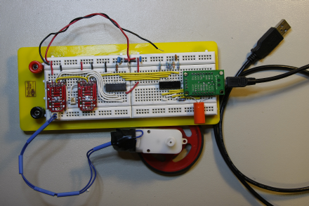
|
|
Top
|
|
|
|
|
#308228 - 14/03/2008 22:59
Re: Electronics help- H-Bridge is annoying me
[Re: mlord]
|
carpal tunnel

Registered: 17/12/2000
Posts: 2665
Loc: Manteca, California
|
Ok! So break out the Altoids tin already. You know You want too.
_________________________
Glenn
|
|
Top
|
|
|
|
|
#308231 - 15/03/2008 00:35
Re: Electronics help- H-Bridge is annoying me
[Re: mlord]
|
carpal tunnel
Registered: 29/08/2000
Posts: 14478
Loc: Canada
|
But for now, I've just reworked the breadboard to shorten wires and the like, and it seems much improved. More later. Mmmm... so long as I use a totally independent power supply for the motor side of the house, it works flawlessly now. Well, except for once in a very blue moon, when I force the motor in reverse while the current tries to drive it the other way, but even then it takes a few dozen attempts to glitch it. That's on our MythTV box, which has an undervoltage PSU (4.8V on the "5.0V" line). On my notebook (which has 5.1V on the 5.0V line) I cannot glitch it in that way. It's good enough now, but I really don't want another wall wart in that room. Powering the motor side directly from the 5V line of the ATX PSU in the box can still glitch it. So I may try a 12V line instead, and use a 7805 to step that down to 5V on the motor board. The saga continues..
|
|
Top
|
|
|
|
|
#308240 - 15/03/2008 02:12
Re: Electronics help- H-Bridge is annoying me
[Re: mlord]
|
carpal tunnel
Registered: 29/08/2000
Posts: 14478
Loc: Canada
|
Mmmm... so long as I use a totally independent power supply for the motor side of the house, it works flawlessly now.
...
It's good enough now, but I really don't want another wall wart in that room. Powering the motor side directly from the 5V line of the ATX PSU in the box can still glitch it. So I may try a 12V line instead, and use a 7805 to step that down to 5V on the motor board. Well, heh.. that was interesting. I created an onboard 5V PSU with a 7805 connected to the 12V ATX supply from the MythTV box. No difference from just using the 5V directly from the ATX box: still glitchy. Despite placing the recommended ceramics (from the 7805 datasheet) right next to the regulator. Oh well, yet another wall wart does seem to be in the works now.. Cheers
|
|
Top
|
|
|
|
|
#308241 - 15/03/2008 02:14
Re: Electronics help- H-Bridge is annoying me
[Re: gbeer]
|
carpal tunnel
Registered: 29/08/2000
Posts: 14478
Loc: Canada
|
Yeah, I really need a storage scope here, to find out what's actually happening. Ok! So break out the Altoids tin already. Yeah, baby.. oh yeah! (just gotta find one that I like, at a reasonable price..). Cheers
|
|
Top
|
|
|
|
|
#308243 - 15/03/2008 04:44
Digital Storage Scopes.. cheap!
[Re: mlord]
|
carpal tunnel
Registered: 29/08/2000
Posts: 14478
Loc: Canada
|
Yeah, I really need a storage scope here, to find out what's actually happening. Ok! So break out the Altoids tin already. Yeah, baby.. oh yeah! (just gotta find one that I like, at a reasonable price..). Well, well.. Tough choice.. The price on the second one seems to vary week by week, from $585 to $799. Currently $674.
|
|
Top
|
|
|
|
|
#308244 - 15/03/2008 05:51
Re: Electronics help- H-Bridge is annoying me
[Re: mlord]
|
enthusiast
Registered: 21/02/2006
Posts: 325
|
Hi,
Shonky is correct about layout problems causing EMI/EMC susceptibility.
A couple of thing to consider when you transfer the design to Printed Wiring Board (PWB).
1) The controller device is CMOS and even though the output of the chip is controlling very slow events, the rise and fall time is usually very fast. I noticed that the design does not include any termination for the lines that drive the motor controller. It is often a good idea to series terminate the lines at the driver side. The termination resistor can be roughly estimated by:
a) Estimate the output impedance of the driver (RO)
R(Out) = V(OL) / I(OL)
Example: The datasheet specifies Normal Drive Output Low
Voltage V(OL) as 0.3V and Low Output Current I(OL) as 2mA.
R(out) = 0.3V / 2mA = 0.3 / 0.002 = 150 Ohm
The wiring you have in your circuit is around 100 Ohms, this
exceeds the 150 Ohm and no series termination should be
required. The worst it will do is degrade the rise and fall
time a little which in your case is negligible.
The output drive strength is programmable. The datasheet also
specifies that it has a high-drive capability of 8 mA at
VCC=3.3V. If it is progammed for high drive (to drive your
opto-isolators), the value of R(Out) is calculated as:
R(Out) = V(OL) / I(OL)
The datasheet specifies Normal Drive Output Low
Voltage V(OL) as 0.3V and Low Output Current I(OL) as 8mA.
R(out) = 0.3V / 8mA = 0.3 / 0.008 = 37.5 Ohm
b) To terminate the line properly (to eliminate reflections that
may cause Overshoot - which may over-Voltage the output driver
power ESD clamps)for the high-drive case, you need to use the
following calculation:
R(Series) = Zo - R(Out) Where:
R(Series) is the series termination resistance value
Zo is the target impedance of the transmission line
(The target impedance of the circuit board - like 50 Ohms)
R(Out) is the output resistance you just calculated above
R(Series) = 100 Ohms (your wire impedance of your breadboard)
R(Out) = 37.5 Ohms (calculated above)
R(series) = 100 Ohms (-) 37.5 Ohms = 62.5 Ohms (use a 68 Ohm)
If you don't need the extra drive for the Opto-isolators,
just program it out.
For your new board layout use the target impedance of board
(preferred 50 Ohm Characteristic Impedance) for Zo in the
formula above.
PWB Board & Routing Recommendations:
------------------------------------
1) Use a 4 layer PWB. You can use a similar stack-up like this:
Layer 1 - Signal Layer 1
Layer 2 - Solid Ground and Routed Power within Ground
Layer 3 - Signal Layer 2
Layer 4 - Ground
If you have to use a 2 layer (increases susceptibility and
emissions), use the following stack-up:
Layer 1 - Signal Layer
Layer 2 - Ground and Routed power within Ground
On Layer 1, use a ground fill with around 10 mil spacing
around the traces. Make sure that the ground fill vias into
the Ground on Layer 2 (don't leave unconnected Ground Islands
on Layer 1. Sometimes it works to drill a hole and solder a
wire from the Ground Island to layer 2 Ground Plane - Vias
work better though. Make sure you don't drill through traces
on Layer 2 though <grin>.
2) Place your sensitive lines in Layer 3 like Reset,
CBUS lines and UART Lines if you use them, & USB Lines. Route
non-sensitive lines on Layer 1 of the 4 Layer Stack-up.
3) Do not route any lines across or adjacent to the Routed Power
Traces or to Reset
4) Route 8 mil traces with 4X the line width space from edge to
edge ie... If your trace width is 8 mils the next trace
adjacent to it is 32 mils away edge-to-edge. This is
conservative, but you don't have a lot of traces, so use the
space. This prevents crosstalk, but if the board is small,
with short traces, you can go down to 2X with no problem.
5) Don't route any of the motor outputs or motor power traces
near the digital traces.
6) Consider a plane split bridged by a Zero Ohm resistor between
the Motor circuitry and the Digital Circuitry to partition
the noise. It is easier to add or remove it. The Opto-
Isolator can easilly cross the boundary, but if you need a
common ground, the Zero Ohm Resistor is easy to install.
Since you have Opto-isolators, no digital return currents
have to cross the boundary and you should be okay.
7) Make the power traces wide (20 mils). As Shonky mentioned,
The decoupling capacitors should be close to the chip. Place
them with the smallest value closer (a 100nF capacitor is
placed closer to the chip than a 10uF capacitor is), to the
chip VCC and via directly into the ground plane(s). The 10 uF
can be placed further away.
8) Place any series resistors at the driver side of the net.
9) Route the motor traces as a Differential Pair as much as
possible if they are long. They do not have to be matched.
10) Route the USB Bus as a Differential Pair on the inside
layer for the 4 layer PWB. If your board is 40 mils or
62 mils thick, space the dielectric layers 8 to each other.
Use 10 mil traces and space them 15 mils away edge to edge
from each other (45 Ohm Characteristic, 90 Ohms
Differential Impedance). Route any Ground around them spaced
12 mils away from the trace pair (for Co-Planar Differential
Striplines).
11) Make sure all of the unused lines are either pulled high or
low unless they affect functionality. One trick if you are
experiencing Ground Bounce issues is to have all of the
unused drivers driving low. This works well with FPGAs with
lots of I/O or I/O banks.
12) If you do use a 7805 off of +12V, place a 10uF capacitor
near the input and another near the output - it needs to see
low ESR on both sides - most linear regulators need this. A
Tantalum Capacitor works best, always select the working
voltage of a Tantalum (you can get by with less with an
electrolytic cap), by multiplying the applied voltage by 2.
ie... 25V cap on the input (2 X 12V), and (2 X 5V) = 10V or
16V on the output.
13) Is there a reason why you didn't connect VCC to VCCIO?
Most design examples have these connected.
14) Make sure you filter the Motor Driver Supply with a Pi
filter of some sort. Like a 0.1uF connected to the +12V
power input, then a Ferrite Bead, then a 0.1uF cap to the
Motor Driver Chip. Remember the Bulk Low Frequency Capacitor
on the Motor Driver Chip side of the Ferrite Bead.
15) Be sure to decouple the power from the USB with a 0.1uF and
10uF to clean it up. This returns your generated noise to
your card and filters off any noise coming to you from the
USB Host.
Ross
_________________________
In SI, a little termination and attention to layout goes a long way. In EMC, without SI, you'll spend 80% of the effort on the last 3dB.
|
|
Top
|
|
|
|
|
#308249 - 15/03/2008 12:50
Re: Digital Storage Scopes.. cheap!
[Re: mlord]
|
carpal tunnel
Registered: 29/08/2000
Posts: 14478
Loc: Canada
|
Well, well.. Tough choice.. Okay, I've ordered the German/UK 200MHz DSO (second link above) -- the specs are really unbeatable at that price, with probes included. Should be here by mid/late next week, I expect. EDIT: looks more like about 2-weeks for delivery now. /EDIT Woo-hoo! (gotta go update the New Toy thread with this info now).
Edited by mlord (15/03/2008 17:39)
|
|
Top
|
|
|
|
|
#308271 - 16/03/2008 01:28
Re: Electronics help- H-Bridge is annoying me
[Re: Ross Wellington]
|
carpal tunnel
Registered: 29/08/2000
Posts: 14478
Loc: Canada
|
Thanks, Ross. I'm still digesting your latest brain dump, but do please keep them coming. I'm sure everyone else here also enjoys them!
Meanwhile, I decided that the only way to improve the layout of my circuit was to scrap the preassembled L293D boards. They are fun to play with, and have blinken lights for debugging and all, but they also lack any attempt at EMI suppression. Not a single cap on board either of them.
My last order from Digikey included a couple of raw L293D chips, so I just plopped them down on the breadboard, and started routing signals again.
This time I was careful to keep the logic and motor power buses completely separate, as well as maintaining the full isolation to the USB sub-assembly.
I applied a generous spinkling of little through-hole ferrite beads, and some little blue capacitors labeled "693M", as well as my limited stock of 0.1uF ceramic discs.
Woo-hoo, it works!
I can power the motor & electronics from the same ATX supply that the PC and USB end use, and have not managed to trip up the USB at all, despite furious attempts to do so.
Here are some photos of the latest layout.
Attachments
 Description: The complete breadboard. USB isolated at the left by the "shiny" quad optoisolator chip. Description: The complete breadboard. USB isolated at the left by the "shiny" quad optoisolator chip. Description: The motor side of the house. Left chip is a 3:8 decoder to provide fan-out from my limited number of GPIO pins. Lots of ferrite beads and pretty blue capacitors, too! The middle H-Bridge is not fully wired up yet; I've only been testing with the rightmost Description: The motor side of the house. Left chip is a 3:8 decoder to provide fan-out from my limited number of GPIO pins. Lots of ferrite beads and pretty blue capacitors, too! The middle H-Bridge is not fully wired up yet; I've only been testing with the rightmost
|
|
Top
|
|
|
|
|
#308336 - 17/03/2008 20:05
Re: Electronics help- H-Bridge is annoying me
[Re: mlord]
|
addict
Registered: 24/07/2002
Posts: 618
Loc: South London
|
We've now switched to isolation routing for in house prototypes, veroboard was taking too much time and effort: 
|
|
Top
|
|
|
|
|
#308337 - 17/03/2008 20:19
Re: Digital Storage Scopes.. cheap!
[Re: mlord]
|
old hand
Registered: 20/07/1999
Posts: 1102
Loc: UK
|
Speaking from personal experience, those breadboard blocks you're using are a sod for crosstalk. I've long since given up using them, as every circuit I was inerested in building on them simply wouldn't work because of the parasitic capacitance or inductance of the things. Also, stop finding useful toys and posting the links! I've just finally completely paid off my credit card, and you go and tempt me with a decent scope at a good price pca
_________________________
Experience is what you get just after it would have helped...
|
|
Top
|
|
|
|
|
#308338 - 17/03/2008 21:34
Re: Digital Storage Scopes.. cheap!
[Re: pca]
|
carpal tunnel
Registered: 29/08/2000
Posts: 14478
Loc: Canada
|
Speaking from personal experience, those breadboard blocks you're using are a sod for crosstalk. I've long since given up using them, as every circuit I was inerested in building on them simply wouldn't work because of the parasitic capacitance or inductance of the things. Yeah. It's particularly bad with those H-bridge chips.. the signal pins are sandwiched between power pins and output driver pins. And most of the signals are paired across the chip (opposite pins tied together, like the cute yellow jumpers above). I can hardly wait to view the carnage once the new scope arrives. Also, stop finding useful toys and posting the links! Ya takes yer chances when reading these postings, Patrick! We'll see if that new rig is any good or not once it arrives here. -ml
Edited by mlord (18/03/2008 01:15)
|
|
Top
|
|
|
|
|
#308339 - 17/03/2008 21:40
Re: Electronics help- H-Bridge is annoying me
[Re: sn00p]
|
carpal tunnel
Registered: 29/08/2000
Posts: 14478
Loc: Canada
|
We've now switched to isolation routing for in house prototypes, veroboard was taking too much time and effort Wow! That looks totally extreme! Like for RF or something. Thanks for posting it! Cheers
|
|
Top
|
|
|
|
|
#308340 - 17/03/2008 22:02
Re: Electronics help- H-Bridge is annoying me
[Re: mlord]
|
addict
Registered: 24/07/2002
Posts: 618
Loc: South London
|
Cool. Glad you liked. That board is totally non exciting though! It's just a uart (TTL level) to 20ma converter (vending machine interface). I knew it'd take ages to do on veroboard, then check and double check...only to find that it didn't work. <tangent> We had a CNC machine made for us, we had a couple of differing requirements. It had to be large enough so we can use it for mechanical prototyping (i.e faceplates and such like) but with also with enough fine resolution to mill pcb's. The machine itself can do pretty large bits and pieces, wouldn't have trouble doing 19inch rack mount panels. But once I'd done all the setting up in mach3 it was a nervous time waiting to see what the accuracy would be like on small things...Thankfully it turned out to be very good. I added isolation routing to our software so that we could directly export a 2 layer design into NC and straight into mach3. </tangent> I was quite pleased that I managed to route the entire board without the need for a single jump wire, single layer as well! Not only was I impressed, but my boss was too. We did another board a few weeks earlier which was an RFID interface, that also worked straight off without any problems. The great thing about this method is that because you're laying out from a schematic you can be certain that the final output will be correct. Just have to put the right components in the right holes. That board (from memory) had 56 odd drill holes that were 0.6mm, 0.7mm, 0.8mm and 1mm in diameter. I think it took me a couple of hours start to finish (design to routing to populating to working!). For small test circuits it's a revolution! We reckon we could do large QFP's without much problem too.
|
|
Top
|
|
|
|
#308345 - 18/03/2008 00:37
 Re: Electronics help- H-Bridge is annoying me
[Re: sn00p]
Re: Electronics help- H-Bridge is annoying me
[Re: sn00p]
|
carpal tunnel
Registered: 29/08/2000
Posts: 14478
Loc: Canada
|
I added isolation routing to our software so that we could directly export a 2 layer design into NC and straight into mach3. Totally cool, that. I was wondering how the layout ended up as an "etched" PCB.. trivial stuff with a CNC machine, once the software exists.. EDIT: Oh, and did I mention that I think you have a rather cool job? 
Edited by mlord (18/03/2008 00:40)
|
|
Top
|
|
|
|
|
#308356 - 18/03/2008 11:44
Re: Electronics help- H-Bridge is annoying me
[Re: mlord]
|
member
Registered: 12/08/2001
Posts: 175
Loc: Atlanta
|
We have a Quick Circuit at work that does a good job. Only problem is that you can't put vias under parts since our vias are just eyelets smashed into the vias. Also, we have all the through hole connections on the back to ensure we can solder to the pins.
The software came with the milling machine, and it takes gerber files and isolates the traces with a specified gap. I believe the system was pretty expensive, about $15k.
|
|
Top
|
|
|
|
|
#308370 - 18/03/2008 17:22
Re: Electronics help- H-Bridge is annoying me
[Re: Folsom]
|
addict
Registered: 24/07/2002
Posts: 618
Loc: South London
|
Oh, you mean like this circuit, from whence I "liberated" a couple of optoisolators for an early prototype of my Frankenswitch V2 circuit:
Yeah, that'll be the same thing!
Totally cool, that. I was wondering how the layout ended up as an "etched" PCB.. trivial stuff with a CNC machine, once the software exists..
EDIT: Oh, and did I mention that I think you have a rather cool job?
Yeah. I'm fortunate that I get to do a lot of different stuff! Originally I just did our pcb software but I also done a lot of embedded stuff for quite a few years now. The software came with the milling machine, and it takes gerber files and isolates the traces with a specified gap. I believe the system was pretty expensive, about $15k.
Ouch! It's a pretty trivial exercise when you figure out how to do it. Took me about a day I think to get the software producing the isolation traces. Our software outputs direct to NC and doesn't require external software to import gerber.
|
|
Top
|
|
|
|
|
#308372 - 18/03/2008 19:40
Re: Electronics help- H-Bridge is annoying me
[Re: sn00p]
|
member
Registered: 12/08/2001
Posts: 175
Loc: Atlanta
|
The software that came with the machine is nice; you specify different isolation widths and it will remove all the ones that overlap. The same software that imports the gerbers also runs the milling machine, so it is all in one suite.
The milling machine is nice, but it sounds like they are changing from milling to laser. The one we have is very loud, and you have to keep changing bits if you want different isolations or hole routing.
|
|
Top
|
|
|
|
|
#308392 - 19/03/2008 15:15
Re: Electronics help- H-Bridge is annoying me
[Re: mlord]
|
carpal tunnel

Registered: 13/02/2002
Posts: 3212
Loc: Portland, OR
|
I'm sure everyone else here also enjoys them! I'd enjoy them a lot more, if I understood what everyone was talking about.  Ah, well. when I get the opportunity, I'll go through the relevant electrical engineering MIT open courses, and then come back and re-read all these posts.
|
|
Top
|
|
|
|
|
#308393 - 19/03/2008 15:35
Re: Electronics help- H-Bridge is annoying me
[Re: canuckInOR]
|
carpal tunnel
Registered: 29/08/2000
Posts: 14478
Loc: Canada
|
I'm sure everyone else here also enjoys them! I'd enjoy them a lot more, if I understood what everyone was talking about. Ah, well. when I get the opportunity, I'll go through the relevant electrical engineering MIT open courses, and then come back and re-read all these posts. Heh.. I'm still a dedicated software/firmware geek, with electronics as a high-school hobby from the very distant past. So I think I understand perhaps half of what's said. I'm going to use the new scope to help me understand the rest. Things like this are a lot easier when one can actually see what's happening, and see the effects of changes to the circuit. Then the theory begins to make more sense. Cheers!
|
|
Top
|
|
|
|
|
#308395 - 19/03/2008 18:01
Re: Electronics help- H-Bridge is annoying me
[Re: mlord]
|
carpal tunnel

Registered: 17/01/2002
Posts: 3995
Loc: Manchester UK
|
Me too, the insides of PIC's and microcontrollers make sense. Interfacing them to other things is where I have to end up googling.
I would love to have done A-Level electronics but my school didn't offer it. I'd love to do an evening class or part-time course in it, but there doesn't seem to be anything in the area and there doesn't appear to be 'one' place on the web to search for it.
_________________________
Cheers,
Andy M
|
|
Top
|
|
|
|
|
#308397 - 19/03/2008 18:14
Re: Electronics help- H-Bridge is annoying me
[Re: andym]
|
carpal tunnel

Registered: 25/12/2000
Posts: 16706
Loc: Raleigh, NC US
|
As was implied earlier, how can you go wrong with free MIT coursework?
_________________________
Bitt Faulk
|
|
Top
|
|
|
|
|
#308398 - 19/03/2008 18:20
Re: Electronics help- H-Bridge is annoying me
[Re: andym]
|
pooh-bah

Registered: 20/01/2002
Posts: 2085
Loc: New Orleans, LA
|
I was able to take 1st and third year electronics in high school. I had to skip year 2 since it was only offered the exact same time as gifted english, which they wouldn't let me out of. The unfortunate bit is that it was really more of a vo-tech class so I was in class with quite a few people that weren't nearly as interested as I was, to put it nicely. One of the guys at my work station missed 3 months of school because he quite literally blew 3 of his fingers off trying to make a homemade grenade in the back yard. The really unfortunate bit for me is that this was all 15 years ago, and I've forgotten 95% of what I learned. Oh well.
|
|
Top
|
|
|
|
|
#308400 - 19/03/2008 20:19
Re: Electronics help- H-Bridge is annoying me
[Re: wfaulk]
|
carpal tunnel
Registered: 17/01/2002
Posts: 3995
Loc: Manchester UK
|
I could also re-read all the books I've collected over the years. IMO nothing compares to sitting in a properly equipped classroom listening to someone who knows what they're talking about.
_________________________
Cheers,
Andy M
|
|
Top
|
|
|
|
|
#308403 - 19/03/2008 22:29
Re: Electronics help- H-Bridge is annoying me
[Re: andym]
|
addict
Registered: 24/07/2002
Posts: 618
Loc: South London
|
Me too, the insides of PIC's and microcontrollers make sense. Interfacing them to other things is where I have to end up googling. I'm usually pretty harsh on PIC microcontrollers. But the other week I actually found myself choosing a PIC for a project, I couldn't believe what I was doing. Thing is, Microchip have got the number of available USB endpoints correct in their "18F" family. We almost exclusively use ARM based processors, but my favoured ARM flavoured chip only has 4 fricking endpoints, which basically means that it can't be used as a composite device. On the other hand, the PIC has 32 endpoints, which is more than enough for the application which we require it for. Fortunately this application requires no processing, just shifting of data in and out - so the PIC will do fine for this. And as a side rant, why exactly does a CDC serial port under windows require a inf file to install? Is this just to extort money from hardware vendors if they don't want security warnings popping up? OS X and Linux handle them quite happily.
|
|
Top
|
|
|
|
|
|


 Previous Topic
 Index
Index