Fixing the temperature sensor!

Posted by: mlord

Fixing the temperature sensor! - 11/02/2008 20:19

Well, with everything else fixed in my empegs (except for one missing cs4231a chip..), I figured I may as well fix the "broken" ds1821 temperature sensors in a couple of them.

The chip isn't really broken, it's just confused -- it thinks it is a thermostat rather than a temperature sensor. To get it back into sensor mode, it has to be re-configured.

This requires a special reprogramming sequence, whereby pin-8 is temporarily grounded while software pulses pin-2 (DQ) low 16 times, and then pin-8 is set to +5V. Software must then write the configuration register of the device to have it remember the setting for subsequent power-ons.

So I wrote a small addition to Hijack to handle the reprogramming, including a prompt for me to switch the voltage on pin-8, and then wired up a 3-pole switch to handle the hardware side. The switch and stuff get removed again once the operation has succeeded.

It worked great on my first unit. Now I just have to identify which other ones also require the fix.

Cheers
Posted by: mlord

Re: Fixing the temperature sensor! - 11/02/2008 20:54

Another one fixed!

It takes way longer to disassemble/reassemble the player than to actually fix the sensor.

Still digging through the collection here..
Posted by: mlord

Re: Fixing the temperature sensor! - 11/02/2008 21:00

Originally Posted By: mlord
Another one fixed!

It takes way longer to disassemble/reassemble the player than to actually fix the sensor.

Still digging through the collection here..

Mmmm.. only the two. I could've sworn there was one more!

So, that was one in four with the problem here.
I wonder if that average is typical ?

(I believe we fixed the cause several years ago, so no new ones should be going bad now, at least not with a modern Hijack installed).
Posted by: Robotic

Re: Fixing the temperature sensor! - 11/02/2008 21:17

The man is on fire!
Go, Mark!
Posted by: canuckInOR

Re: Fixing the temperature sensor! - 12/02/2008 00:47

Originally Posted By: mlord
Now I just have to identify which other ones also require the fix.
Well... mine, for one. crazy
Posted by: newguy1

Re: Fixing the temperature sensor! - 12/02/2008 01:56

Is this a permanent fix, or will the chip get confused again?
Posted by: mlord

Re: Fixing the temperature sensor! - 12/02/2008 02:03

Originally Posted By: newguy1
Is this a permanent fix, or will the chip get confused again?

"I believe we fixed the cause several years ago, so no new ones should be going bad now, at least not with a modern Hijack installed".

The story was, that while clocking commands out to read temperatures, the routine used to be interrupted once in a while by the "DMA" interrupt (moving sound bits to the DSP). This causes the ds1821 to misinterpret those pauses as phantom bits. Once in a while it would "get lucky", and those "phantom bits" would tell it to switch to thermostat mode. Permanently.

We fixed that by masking all interrupts (including the "DMA" interrupt, aka. FIRQ) during any bit-banging operations for the ds1821 chip. Problem solved.

Cheers
Posted by: mlord

Re: Fixing the temperature sensor! - 12/02/2008 02:25

Mmmm.. there may be a slightly simpler way to do this.

The SMC ethernet chip has a spare TTL-output pin (as well as a spare input), which could be wired to pin-8 of the ds1821 temperature sensor chip. Then the pull-down to GND, and subsequent pull-up to Vdd could be accomplished automatically by Hijack.

Just a simple pin-lift + jumper wire. And it could be left in place permanently.

I think I'll "kill" another temperature sensor here and try that mod on it..
Posted by: mlord

Re: Fixing the temperature sensor! - 12/02/2008 03:04

Originally Posted By: mlord
Mmmm.. there may be a slightly simpler way to do this.

The SMC ethernet chip has a spare TTL-output pin (as well as a spare input), which could be wired to pin-8 of the ds1821 temperature sensor chip. Then the pull-down to GND, and subsequent pull-up to Vdd could be accomplished automatically by Hijack.

Just a simple pin-lift + jumper wire. And it could be left in place permanently.

I think I'll "kill" another temperature sensor here and try that mod on it..


Or not. The current fix is simple enough for me.

Hijack v486 is now released, with the source code for the above fix included (but not compiled-in by default), so that I don't lose track of it here!

Cheers
Posted by: Redrum

Re: Fixing the temperature sensor! - 12/02/2008 11:21

Originally Posted By: Robotic
The man is on fire!
Go, Mark!


It must be realy cold or snowy in Canada this year. smile
Posted by: mlord

Spare general purpose input/output pins! - 12/02/2008 14:20

Originally Posted By: mlord
The SMC ethernet chip has a spare TTL-output pin (as well as a spare input), which could be wired to pin-8 of the ds1821 temperature sensor chip. Then the pull-down to GND, and subsequent pull-up to Vdd could be accomplished automatically by Hijack.

Just a simple pin-lift + jumper wire. And it could be left in place permanently.

This one is still nagging at me. I'd like to make the sensor fix simple enough that just about anyone here could do it easily, with modest soldering skills. It's not bad right now, but does require the special Hijack load and a somewhat timely manual switch toggle.

If we used the spare output from the ethernet chip, then just a pin lift and jumper would be needed, and the rest could be stock and automatic. But then.. anyone who can accomplish the pin lift, could probably handle the existing procedure too.

So.. about that ethernet chip..

The SMC LAN91C96 chip actually has several spare in/out pins. They're not "GPIO", in the sense that they are fixed as either inputs or outputs. But they are there, and unused.

Pins 96,97,99 are IOS0,IOS1,IOS2 --> general purpose TTL input pins, which Patrick was kind enough to factory equip with 10K pull-ups and pads for an unpopulated pin header ("PL9" pins 1-3, plus GND on pin 4).

Pin 3 is also a general purpose TTL input pin, with an internal pull-down (floats to zero on no-connect).

Pins 2,4 are general purpose TTL outputs (capable of 2mA source, or 4mA sink).

Those are all accessible through the ethernet chip's internal registers.
So.. I wonder what other good uses they might have ?
Posted by: mlord

Re: Spare general purpose input/output pins! - 12/02/2008 14:58

..and GPIO5 of the CPU chip could be made available, I think.

It is currently wired to the DSP_OUT2 pin of the DSP (through an inverter), but I don't see it actually being used anywhere in the kernel. So we could likely disconnect it and re-use it for something else if we wanted to. This is a real GPIO pin.
Posted by: altman

Re: Spare general purpose input/output pins! - 15/02/2008 00:16

Personally if I was soldering around there I'd just jam an LM77 in there instead.I have actually no idea why we didn't just use the LM77 at the time, I think both myself and Patrick had a severe case of datasheet blindness....

smile

Hugo
Posted by: mlord

Re: Spare general purpose input/output pins! - 15/02/2008 01:16

Yeah, perhaps. But we know what used to make the ds1821 go bad, and fixed it ages ago, so nowadays that chip is plenty good enough there! (even though it is dog slow to access..)

Cheers
Posted by: gbeer

Re: Spare general purpose input/output pins! - 20/02/2008 00:57

Quote:

So.. I wonder what other good uses they might have ?


tongue in cheek... Expanded Memory
Posted by: mlord

Re: Spare general purpose input/output pins! - 04/03/2008 21:42

Originally Posted By: mlord
If we used the spare output from the ethernet chip, then just a pin lift and jumper would be needed, and the rest could be stock and automatic. But then.. anyone who can accomplish the pin lift, could probably handle the existing procedure too.

So.. about that ethernet chip..

The SMC LAN91C96 chip actually has several spare in/out pins. They're not "GPIO", in the sense that they are fixed as either inputs or outputs. But they are there, and unused.

Pins 96,97,99 are IOS0,IOS1,IOS2 --> general purpose TTL input pins, which Patrick was kind enough to factory equip with 10K pull-ups and pads for an unpopulated pin header ("PL9" pins 1-3, plus GND on pin 4).

Pin 3 is also a general purpose TTL input pin, with an internal pull-down (floats to zero on no-connect).

Pins 2,4 are general purpose TTL outputs (capable of 2mA source, or 4mA sink).


I tried fiddling with this stuff today.. it worked fine for automatically repairing the temperature sensor, but..

But.. the ethernet driver performs gratuitous resets of the ethernet chip periodically, including twice at boot. And every time it does this, it messes up the ds1821 temperature sensor.

So, these ouput lines are pretty useless.

Cheers
Posted by: LittleBlueThing

Re: Spare general purpose input/output pins! - 05/03/2008 07:13

Originally Posted By: mlord

But.. the ethernet driver performs gratuitous resets of the ethernet chip periodically, including twice at boot. And every time it does this, it messes up the ds1821 temperature sensor.

If only we had the source... wink
?


Or are they closer to required than gratuitous?
Posted by: mlord

Re: Spare general purpose input/output pins! - 05/03/2008 12:28

Originally Posted By: LittleBlueThing
Originally Posted By: mlord

But.. the ethernet driver performs gratuitous resets of the ethernet chip periodically, including twice at boot. And every time it does this, it messes up the ds1821 temperature sensor.

If only we had the source... wink

Heh.. if only we understood the source! smile

Quote:
Or are they closer to required than gratuitous?


Exactly.
Posted by: mlord

Fixing your own temperature sensor - 06/03/2008 03:16

A couple of people have expressed interest privately in attempting this fix on their own. It's not too difficult, so here are more detailed instructions for those with soldering skills.

First, install this special version of Hijack on your player. After rebooting, you should see a new Hijack menu item, Fix Temperature Sensor, but don't use it yet.

Now disassemble your player, almost completely. Remove the front fascia, buttons, and lens, and the hard drive tray. Remove the front display completely, by undoing the four little screws (two on each side of the player), similar to the screws for the drive tray. There is no need to remove the main board, but the display has to come completely out (it's in the way).

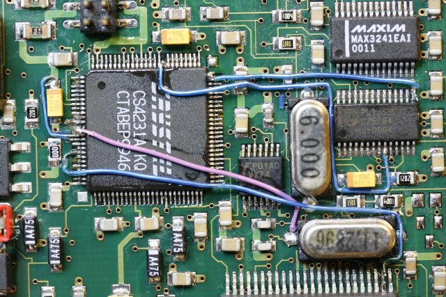
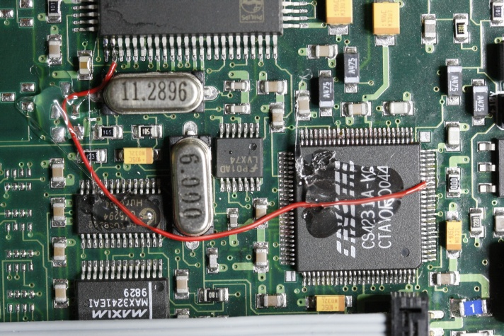
Now locate the ds1821 chip, using the photos from earlier in this thread.. the chip is normally hidden under the display cable.

Examine the photos from earlier in this thread again, and identify pin-8 -- the one I have lifted and attached the blue wire to.

Desolder and lift pin-8 of the ds1821 chip in your player. This is the only difficult part of this repair. If you screw up, the worst that can happen is you will break the pin, and have to replace the entire chip (about $6 from digikey.com, plus S&H).

Fortunately, pin-8 is a corner pin, so access to it is much easier than for most other pins. There's no perfect way to accomplish this, but what I do is:
  • use a 650 degree fahrenheit (343 Celsius) soldering iron.
  • use a 1/32" tip (or finer).
  • apply flux to pin-8 of the chip.
  • put a tiny bead of solder on the iron tip.
  • apply the iron to the pad on the board for pin-8.
  • grab/lever pin-8 up and out with fine tweezers or an Xacto knife.
  • do not take too long here, or you may overheat the board and ruin the pad permanently.
  • remove soldering iron, and use tweezers to gently straighten the pin and bend it up to at least horizontal.

Whew.. that's the tough bit done. Now get a DPST (or DPDT) switch of any kind, and a pair of alligator clip jumper wires.

Solder a very slender 6"/15cm (or longer) wire onto the center contact of the switch, and lightly solder the other end of the wire to pin-8 of the chip. This temporary joint doesn't need to be strong, but the wire does have to make some contact with the pin. If you have very small test clips, use those instead of soldering.

Connect alligator clips between one side contact of the switch and the case of the empeg. Just like the green clips in my earlier photo. Easy.

Locate the pair of blue jumpers near the back/center of the empeg mainboard. Remove (either) one of those jumpers to expose the two pins under it. These pins are at +5V when the empeg is powered. Verify this with a volt meter if you are at all uncertain.

Use a second set of alligator clips to connect the other side of the switch to those +5V pins on the empeg mainboard (see the yellow connections I used in the photo).

The resistor I used (in photo above) is probably not necessary, but if you want, you can add one: it goes between the +5V and center contacts of the switch. Anything from 1K to 10K is fine. This keeps pin-8 from floating randomly for a brief instant when the switch position is being changed.

Now set the switch to the +5V position, and reconnect the empeg display to the mainboard. Be *very* careful that the display connector is properly aligned and the right way around, or you'll blow some SMT fuses and maybe other stuff!!

Power on the empeg, no hard drives are needed.

Now move the switch to the grounded position.

Push and hold the knob until the Hijack menu appears.

Select Fix Temperature Sensor from the menu. It will then prompt you to move the switch to the +5V position. Do so, and then give the front-panel knob a gentle twist to the right.

The Hijack High Temperature Warning screen should then appear. Wait 5 seconds or so, and then verify that the temperature reading (the "Currently" line) shows a realistic value near room temperature, plus or minus 10 degrees. If not, then move the switch back to Ground, and repeat the Fix Temperature Sensor procedure again until it works.

Once you see valid temperature readings, power off the empeg, remove all of your jumpers/wires, and prepare to resolder pin-8 of the chip:
  • Reinstall the blue +5V jumper you removed earlier!
  • Apply more flux to pin-8 and the pad to which it will be resoldered.
  • Push the pin-8 down onto the pad.
  • Apply the soldering iron tip to the pin, and push it onto the pad firmly but not abusively. It should stick and stay.
  • Remove the soldering iron from the pin.

Use a magnifier to inspect the chip, and see if solder has bridged onto the adjacent pin. Hopefully not. If it has, then apply more flux, and use some fine copper de-soldering braid (with the soldering iron) to remove the excess solder -- this works extremely well when done gently.

Check again for a bridged solder joint. Use an ohm-meter if possible, to ensure that pins 7 and 8 are not connected. Actually, this doesn't really matter, since pin-7 is a "no connect" pin, so don't fuss over it too much if things are being stubborn.

Clean the flux from around/on the chip using a Q-tip swab and some alcohol (100 proof or better; consume any excess! smile ).

Reattach the display board and verify that everything still works. Then re-install the latest version of Hijack, replacing the special one you installed for this procedure.

Cheers
Posted by: woops

Re: Fixing your own temperature sensor - 06/03/2008 18:06

mlord,

Once again you've really done an A+++ job! Thank you so very much.

Your procedure was written perfectly. I did have to try a few times, but when i started the switch at 5+ instead of ground, shut it off, then did the right procdure, the sensor was awoken!

Thanks mlord.
Posted by: mlord

Re: Fixing your own temperature sensor - 06/03/2008 18:15

Originally Posted By: woops
mlord,

Once again you've really done an A+++ job! Thank you so very much.

Your procedure was written perfectly. I did have to try a few times, but when i started the switch at 5+ instead of ground, shut it off, then did the right procdure, the sensor was awoken!


Okay, just in case that sequence also works better for others, I've updated the lengthy-sounding procedure above to match.

Cheers
Posted by: woops

Re: Fixing your own temperature sensor - 07/03/2008 12:14

mlord,

please mention:

once you solder the small wire to the #8 leg of the chip and you are ready to reattach the display cable note:

the display cable goes right over the wire you just soldered to #8 and may push this wire down, THEREFORE, don't cut a large lead for this end and put some cardboard under the solder joint so there is no chance this joint/wire will touch other components. just be careful about this issue.
Posted by: mlord

Re: Fixing your own temperature sensor - 07/03/2008 12:29

Originally Posted By: woops
mlord,

please mention:

once you solder the small wire to the #8 leg of the chip and you are ready to reattach the display cable note:

the display cable goes right over the wire you just soldered to #8 and may push this wire down, THEREFORE, don't cut a large lead for this end and put some cardboard under the solder joint so there is no chance this joint/wire will touch other components. just be careful about this issue.


I used a small enough wire here that this wasn't a problem, though it could be if pin-8 were bent too high up.

Note that the adjacent pin-7 is a no connect pin, though, so it doesn't harm anything if it accidently contacts the modified pin-8.

Thanks for helping me help others here!

Cheers
Posted by: Waterman981

Re: Fixing your own temperature sensor - 07/03/2008 13:25

Well after lifting pin 8 I broke it. I think my small alligator clips I was using moved it. So just to confirm, this is the correct part right? So with replacing the sensor I don't need to do the fix procedure again correct? It should "just work."
Posted by: mlord

Re: Fixing your own temperature sensor - 07/03/2008 13:51

Originally Posted By: Waterman981
Well after lifting pin 8 I broke it. I think my small alligator clips I was using moved it. So just to confirm, this is the correct part right? So with replacing the sensor I don't need to do the fix procedure again correct? It should "just work."


Yes, and yes.

Cheers
Posted by: woops

Re: Fixing your own temperature sensor - 14/03/2008 21:33

Mark,

After the "journey to the deep abyss" and back - ie. diagnosing ethernet problems which involved reformatting both drives, trying v3, v2 individually and in combinations, I have discovered the temperature sensor has gone dead again.

Is it your opinion that the leg of the chip can be bent up again without breaking? If it breaks, how bad off would I be? Can i just leave it broken?

I definitely want to fix it again. What could have caused it to go dead again?

Thanks
Posted by: tman

Re: Fixing your own temperature sensor - 14/03/2008 21:47

Originally Posted By: woops
If it breaks, how bad off would I be? Can i just leave it broken?

The chip would be dead. Pin 8 is Vdd.

Originally Posted By: woops
I definitely want to fix it again. What could have caused it to go dead again?

The problem is only fixed in Mark's kernel I believe. If you used the stock ones then there is a chance that it would screw it up again.
Posted by: mlord

Re: Fixing your own temperature sensor - 15/03/2008 00:40

Originally Posted By: woops
Mark,

After the "journey to the deep abyss" and back - ie. diagnosing ethernet problems which involved reformatting both drives, trying v3, v2 individually and in combinations, I have discovered the temperature sensor has gone dead again.

Yeah, the non-Hijack kernels can do that -- Hijack has the necessary fixes (we think) to prevent it.

Quote:

Is it your opinion that the leg of the chip can be bent up again without breaking? If it breaks, how bad off would I be? Can i just leave it broken?

Just be nice to it, and not bend it more than needed. I've done it four times now to beater here, as part of my experiments, and the pin is still alive. If it breaks though, no big deal -- the chip would simply be dead and not affect anything else.[/quote]

If you (or anyone else) sees one go dead while running a modern Hijack kernel, we want to know about it.

EDIT: Actually, I suppose it's possible in theory to maybe corrupt the chip just from reboot accidents, if done while software is in the midst of talking to the chip. Very unlikely, but remotely possible. Power-offs shouldn't be able to do it, but reboots.. maybe. The power pin of that chip really should have been wired to the !RESET signal instead of to Vcc3.

Cheers
Posted by: mlord

Re: Fixing your own temperature sensor - 15/03/2008 00:46

Originally Posted By: mlord
Just be nice to it, and not bend it more than needed.

You can move the odds more in your favour by only bending the pin from the midpoint, rather than from where it disappears into the chip.. That way, if it ever does snap off, you've still got half a pin left to work with. And that top half doesn't need to be bent because it's already lifted! smile

Cheers
Posted by: woops

Re: Fixing your own temperature sensor - 15/03/2008 11:47

Mark,

Is it possible to go ahead and wire it to the reset signal?
Posted by: mlord

Re: Fixing your own temperature sensor - 15/03/2008 12:03

Originally Posted By: woops
Mark,

Is it possible to go ahead and wire it to the reset signal?


I have not tried this here, but it should work just fine on the the same DSP reset pin that I used for the cs4231a fix (see photo in that thread).

You'll still need to do the pin-lift and reprogram the chip first, though.

Cheers
Posted by: woops

Re: Fixing your own temperature sensor - 15/03/2008 15:07


Mark,

So I am looking to solder the Temperature Sensor #8 pin to the Lower Right Blue Wire solder location of the attached picture you took. Is this correct?

Do I leave the #8 leg of the temperature sensor unsoldered and just wire it to the DSP location?

I assume I can follow the same soldering instructions as you gave for the Temperature Sensor fix? ie: 650 degree iron temp.

Thanks
Posted by: mlord

Re: Fixing your own temperature sensor - 15/03/2008 17:33

Originally Posted By: woops
So I am looking to solder the Temperature Sensor #8 pin to the Lower Right Blue Wire solder location of the attached picture you took. Is this correct?

This other photo shows the correct wire better:


Quote:
Do I leave the #8 leg of the temperature sensor unsoldered and just wire it to the DSP location?

Yes, that's the idea, anyway. Untested as of yet! smile

Quote:
I assume I can follow the same soldering instructions as you gave for the Temperature Sensor fix? ie: 650 degree iron temp.

Yes, maybe even lower -- try 600 degree max, and don't hang around on the pin for more than a few seconds at a time. Breaking the DSP is more serious than the temperature sensor!

Posted by: mlord

Re: Fixing your own temperature sensor - 15/03/2008 17:37

Actually, try poking around with an ohm-meter, and see if you can find the same DSP-RESET value on a nearby capacitor -- much less risky to try attaching it somewhere like that, and there probably *is* a cap on that line somewhere not far away.

Cheers
Posted by: woops

Re: Fixing your own temperature sensor - 15/03/2008 19:00

Mark,

I wouldn't know how to do that. I've got an Ohm-meter though.

Posted by: mlord

Re: Fixing your own temperature sensor - 16/03/2008 01:09

Originally Posted By: woops
Mark,

I wouldn't know how to do that. I've got an Ohm-meter though.


Ah well, you might as well learn how then!

1. Unplug the empeg from everything.

2. Set the ohmeter to its lowest ohm value scale (mine has 200ohms as the lowest).

3. Study the board (or the photo above), looking for small yellowish things with two metal end contacts, within an inch or so of the corner of the DSP where the RESET pin is located.

4. Place one probe from the meter firmly onto the metal end of one of the capacitors you identified, and touch the other end to the dsp RESET pin, and see if the ohmmeter reads "0" when you do so.

If yes, then you've found an alternate site to attach your jumper from thermo pin-8 onto. Otherwise, try the other end of that same capacitor. And then another capacitor, and so on.

Takes about a minute to do them all -- there's only four or five nearby, I think.

Cheers
Posted by: woops

Re: Fixing your own temperature sensor - 16/03/2008 18:24

Mark,

I couldn't find any nearby yellow capacitor ends that had an open to the dsp reset pin.

Also, and i may have done something wrong, but soldering to the dsp reset pin and #8 leg of the temperature sensor gave the i2c error unable to get data and would not play music. Understand that i had previously reset the temperature sensor to work again as you have previously outlined and lifted leg #8 to only tie in with the dsp reset pin

Anyway, I set everything back and it all works - music and temperature - but it has been an arduous journey.

CAUTION: Be VERY careful of how the leg #8 is bent up and how it is twisted, it is not robust at all. You really need to know what you are doing. I broke mine off and had to build up a "solder wall" to reach from the pad to the nub that was left. Very tedious and hard to do. Thankfully, i have a temperature regulated soldering iron i got from radio shack that works really well (used 600 degrees as recommended by Mark).
Posted by: mlord

Re: Fixing your own temperature sensor - 16/03/2008 20:11

Originally Posted By: woops
.. soldering to the dsp reset pin and #8 leg of the temperature sensor gave the i2c error unable to get data and would not play music. Understand that i had previously reset the temperature sensor to work again as you have previously outlined and lifted leg #8 to only tie in with the dsp reset pin


Ah well, so much for that idea.

Clever use of building up the solder stack -- small thin wire can also be used in situations like that.

One time, I had to use an Xacto knife to dig away a little plastic from the shell of a chip, to expose some metal of a broken-off pin so that I could attach a small wire to it.

Cheers!