#370493 - 09/02/2018 00:58
 Re: BlueGigaEmpeg
[Re: tfabris]
Re: BlueGigaEmpeg
[Re: tfabris]
|
carpal tunnel

Registered: 29/08/2000
Posts: 14475
Loc: Canada
|
.. I'll get some true 1.5k resistors in shortly to try that. Tony, if you haven't already done so, I suggest you stop going piecemeal for resistors and just get a full assortment to experiment with. Eg. $8 resistor assortment on Amazon.
|
|
Top
|
|
|
|
|
#370494 - 09/02/2018 02:06
Re: BlueGigaEmpeg
[Re: mlord]
|
carpal tunnel

Registered: 20/12/1999
Posts: 31565
Loc: Seattle, WA
|
I have more than one bagful of resistors, just never the exact values I need.  But yeah, you're right, I should grab another assortment like that. Of course each time I settle on a design for this thing I think I've decided on the exact number of resistors I need of a given type, only to have the design change out from under me.
|
|
Top
|
|
|
|
|
#370498 - 11/02/2018 21:56
Re: BlueGigaEmpeg
[Re: tfabris]
|
carpal tunnel
Registered: 20/12/1999
Posts: 31565
Loc: Seattle, WA
|
Current status: - Three working and completed BlueGigaEmpeg assemblies, including my own prototype unit. All of them use the 7.5 volt Pololu power supply, and 1.5k resistors for the I2S voltage dividers. No pops observed in the audio from any of them, they are all working perfectly and I'm so thrilled. - I have three working Betz boards, all of which required some funky jumpering to get working, some required more jumpering than others. I am undecided as to whether or not I want to sell someone a funky jumpered Betz board, or if I would rather wait for his next production batch to arrive from China so that I'm selling un-funky boards to you fine folks. - I've got enough components in stock to assemble a total of nine sellable assemblies, not counting the Betz boards. - I await the final enclosure box design from Shapeways. I have an enclosure here that has some problems which I've corrected in the next design. A testprint of the corrected design is in production at Shapeways and I should have it in a few days. If that fits perfectly, I'll place an order for the remaining nine, and have them here a couple weeks after that. Mark, thanks again, so much, for the tips about reducing those voltage divider resistors to get rid of the noise. Attached: Photo of three working assemblies. Note that they are a mishmash combination of prototype and final hardware, hence the differences between them. Home stretch! 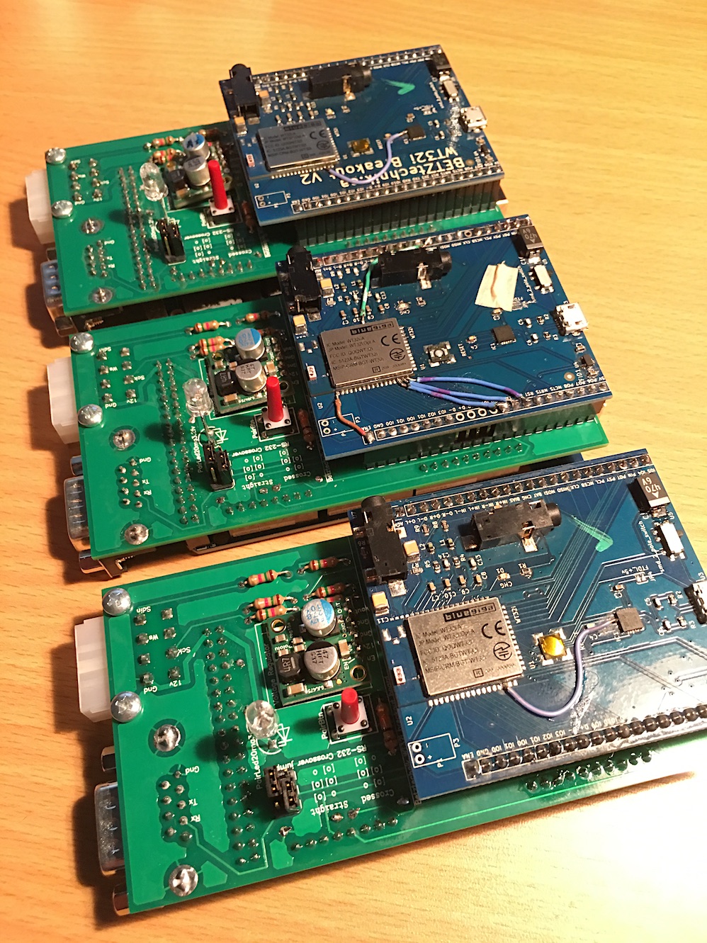
|
|
Top
|
|
|
|
|
#370499 - 12/02/2018 03:23
Re: BlueGigaEmpeg
[Re: tfabris]
|
carpal tunnel
Registered: 29/08/2000
Posts: 14475
Loc: Canada
|
Looks good!
My one suggestion: Drop some goop (hot-melt glue, epoxy, or silicone) on the wire jumpers, to give them some vibration-proofing for car use.
Cheers
|
|
Top
|
|
|
|
|
#370508 - 13/02/2018 22:23
Re: BlueGigaEmpeg
[Re: tfabris]
|
carpal tunnel
Registered: 20/12/1999
Posts: 31565
Loc: Seattle, WA
|
Another EE question, Mark. On my current PCB version, which appears to be working just fine with three different Betz boards, I'm applying 3.3v to the BATT, ENA, and 3v3 connections on the Betz board. According to Peter's schematic, that looks to me like I've got 3.3v sitting on both the VIN and VOUT sides of that little 2.5v voltage regulator ("U4") on his board, regardless of which position I set the "smd_2_pole_switch" to. Why does this work without any apparent ill effects?
|
|
Top
|
|
|
|
|
#370509 - 14/02/2018 02:04
Re: BlueGigaEmpeg
[Re: tfabris]
|
carpal tunnel
Registered: 20/12/1999
Posts: 31565
Loc: Seattle, WA
|
Update: Just ordered a new set of boards from BetzTechnik who just got his shipment in from China. I expect to have my final test print of the enclosure approximately Thursday, and if it's awesome and perfect, then I'll order a set of them right away to fulfill current orders from this thread. So I'll likely be ready to take orders and start packing and shipping completed modules probably in a couple of weeks, depending how how the enclosure turns out and how long it takes to get them to me.
|
|
Top
|
|
|
|
|
#370510 - 14/02/2018 02:44
Re: BlueGigaEmpeg
[Re: tfabris]
|
carpal tunnel
Registered: 29/08/2000
Posts: 14475
Loc: Canada
|
According to Peter's schematic, that looks to me like I've got 3.3v sitting on both the VIN and VOUT sides of that little 2.5v voltage regulator ("U4") on his board, regardless of which position I set the "smd_2_pole_switch" to. Why does this work without any apparent ill effects? Somebody else will have to answer that one!
|
|
Top
|
|
|
|
|
#370512 - 14/02/2018 04:14
Re: BlueGigaEmpeg
[Re: tfabris]
|
pooh-bah
Registered: 12/01/2002
Posts: 2009
Loc: Brisbane, Australia
|
Well the schematic says 2V5 but the part is a 3.3V regulator - that might be just a schematic error and it's a 2.5V part fitted. It's low drop out regulator so with low load, it could have 3.3V in and basically the same out. It's also labelled as 3V3 on P1.
All the switch does is connect the battery.
If in position 2-3 there really should be nothing on pin 3 of U4 assuming that's the entire schematic the the "ON" net is entirely within that dotted line.
If this is not the case, the schematic is wrong or perhaps U4 has failed due to having a voltage applied on its output and pin 2 is somehow shorted to pin 3.
_________________________
Christian
#40104192 120Gb (no longer in my E36 M3, won't fit the E46 M3)
|
|
Top
|
|
|
|
|
#370516 - 14/02/2018 06:31
Re: BlueGigaEmpeg
[Re: Shonky]
|
carpal tunnel
Registered: 20/12/1999
Posts: 31565
Loc: Seattle, WA
|
Thanks, Shonky!
Let me clarify the question a bit, to give you some more context.
The Betz board is indeed using a 2.5v linear voltage regulator at position U4, and in the past I have measured it at 2.5v when the board is all by itself and getting its power from its USB connector. Peter has deliberately designed his board to run the chip at 2.5v in order to make it use less battery for situations where it's battery-powered. The schematic isn't wrong, and there's no damage or failure, the board works fine as is.
What I'm saying is that I, in my PCB design which attaches to this Betz board, am doing things differently, on purpose. Here's what I'm doing:
- Deliberately choosing to run the whole thing "always-on".
- Deliberately choosing to run it at 3.3v instead of 2.5v.
- Deliberately choosing not to use a battery at all and instead running the thing at constant DC supplied 3.3 volts.
To get this to work, I must personally apply 3.3 volts to the following three pins at the edge of the Betz board:
- BATT
- ENA
- 3v3
- I'm also cutting JP4, the "5v power" enabler for the FTDI Uart chip.
- I'm also very carefully NOT applying 5v to the Vin pin on the edge of the board, and not connecting a USB cable to it.
Those things are what's required for me to make this thing work as an "always on" device at 3.3v.
When I apply 3.3 volts to those three pins I listed above, that means that, as far as I can tell from the schematic, I'm applying 3.3v to both sides of that 2.5v linear regulator at position U4. Simultaneously I'm making the little on/off switch totally useless since the 3.3 volts is now going to both sides of the switch anyway no matter what.
As far as I can tell, everything works this way. At least, everything works the way I want it to work. There's no failures occurring here as far as I can tell, everything seems healthy.
So my questions essentially are "why is it fine with this"?
More specifically:
- If I am deliberately applying 3.3 volts to those three pins as I described above, are my assumptions about where the 3.3 volts goes true?
- If true, why does it work? Why don't I have problems because I'm putting 3.3 volts to both sides of that linear regulator at U4? Mark has previously talked about problems occurring when I try to put two "output" voltages into the same place. Why isn't that causing a problem here?
Really this boils down to a single generic question:
- If I have a linear regulator of that type, with a 5v input and a 2.5v output, what is the expected behavior when instead I apply 3.3v to both its input and output lines, and why?
If I think of a linear regulator as just a way to reduce voltage like the voltage dividers we've previously discussed, then it makes sense that the regulator would just "do nothing" in that case, there's the same current on either side of it so there's nothing for it to do. Is that really what's happening here? Or am I misunderstanding how one of those linear regulators works?
|
|
Top
|
|
|
|
|
#370529 - 15/02/2018 04:38
Re: BlueGigaEmpeg
[Re: tfabris]
|
pooh-bah
Registered: 12/01/2002
Posts: 2009
Loc: Brisbane, Australia
|
In my opinion the schematic is definitely wrong since it shows a net as both 2V5 (on the net) and 3V3 (P1) at the same time plus the part number is for a 3V3 regulator. Sure you can select the voltage what you want but that's not noted anywhere. Asking for trouble in any kind of significant production.
Generally you shouldn't apply a voltage to a regulator's output.
If you are applying 3.3V to BATT and to the "3V3" net on P1 then that is both sides of the regulator if U5 1-2 is connected. Actually ON and ENA are connnected via the jumper U5 so if you have both on 3V3 then that explains completely what you're seeing.
So basically you're applying 3.3V on both in and out of the regulator. Results are "undefined" but unlikely to be anything you can see. That's really the result of your final question. Absolute worst case the regulator might eventually fail and short the OUT line to IN (not issue for you) or ground which will short out your supply. Unlikely though.
This regulator is an inline FET and current sense resistor. So shorting it out won't really do anything to it.
_________________________
Christian
#40104192 120Gb (no longer in my E36 M3, won't fit the E46 M3)
|
|
Top
|
|
|
|
|
#370532 - 15/02/2018 19:03
Re: BlueGigaEmpeg
[Re: Shonky]
|
carpal tunnel
Registered: 20/12/1999
Posts: 31565
Loc: Seattle, WA
|
Thanks so much for your detailed answer, Shonky!
The fact that the behavior is "undefined", but unlikely to be a problem, is excellent news for me.
Double checking the schematic... By Jove, you're right, he lists the 3.3v part number for that linear regulator, but the schematic says its output is 2.5v.
I think the mistake is the part number on the schematic. I'm pretty sure he's using a 2.5v part in that location, and he's doing it on purpose. Not entirely certain why, but my assumption has been that it's to use less battery. I think he just forgot to update the part number when he made that change. I'll notify him about it now.
The reason it still says "3v3" on the pin of the schematic on the "P1" connector is because that's the breakout pin for "VDD_IO" on the BlueGiga chip, which nominally accepts 3.3v. But from what Mark and I could tell, he's deliberately only putting 2.5v there with his choice of linear regulator chip.
I just retested the three boards I have, which have all spent quite a lot of time with 3.3v applied to either side of that linear regulator, and on all three boards, the regulator is still working fine when I switch the board back to its default mode. I think if it was going to short out, all three of them would have done so by now. So no worries!
Thanks so much!
|
|
Top
|
|
|
|
|
#370533 - 15/02/2018 19:41
Re: BlueGigaEmpeg
[Re: tfabris]
|
carpal tunnel
Registered: 20/12/1999
Posts: 31565
Loc: Seattle, WA
|
I was nearly correct. Indeed he is intending to use a 2.5 part in that location, I merely had the reason for the part number mixup incorrect. The reason the part number is wrong on the schematic is because that was just the part number associated with the symbol in his CAD software. The actual part number he's using is MCP1700T-2502E/TT.
|
|
Top
|
|
|
|
|
#370535 - 16/02/2018 00:08
Re: BlueGigaEmpeg
[Re: tfabris]
|
pooh-bah
Registered: 12/01/2002
Posts: 2009
Loc: Brisbane, Australia
|
Yeah well he should still and can update the schematic. Almost every schematic design program has a designator e.g. U4 and then one or more component data fields which can be edited. Usually these contain part numbers or at least descriptions. There's no reason to not changed it really other than it got swapped out later on and updating the schematic was too much effort. Similarly the 3V3 on P1 should change as that's what's there not what some other board expects. Nit picking a bit In all I'd be perfectly comfortable shorting across the FET/resistor in the regulator (although I looked the internals for the specified part number and it seems he's replaced it with something else that is pin compatible). Worst case if it somehow fails and causes issues, just remove it.
_________________________
Christian
#40104192 120Gb (no longer in my E36 M3, won't fit the E46 M3)
|
|
Top
|
|
|
|
|
#370536 - 16/02/2018 00:14
Re: BlueGigaEmpeg
[Re: tfabris]
|
pooh-bah
Registered: 12/01/2002
Posts: 2009
Loc: Brisbane, Australia
|
Had a look at the replacement part and it's just a FET that's shown (but has some form of current limiting). It will be fine.
_________________________
Christian
#40104192 120Gb (no longer in my E36 M3, won't fit the E46 M3)
|
|
Top
|
|
|
|
|
#370537 - 16/02/2018 04:07
Re: BlueGigaEmpeg
[Re: Shonky]
|
carpal tunnel
Registered: 20/12/1999
Posts: 31565
Loc: Seattle, WA
|
Super cool!!!
Thank you so much!!!
|
|
Top
|
|
|
|
|
#370538 - 16/02/2018 04:15
Re: BlueGigaEmpeg
[Re: tfabris]
|
carpal tunnel
Registered: 20/12/1999
Posts: 31565
Loc: Seattle, WA
|
Today I got started on soldering several new boards. I got notification that the new Betz boards are on the way and should be here soon. Got the final test print of the enclosure. Works perfect, so Ill be ordering the rest of the enclosures very soon. Shot a short demo video and will be posting that soon. Able to take payment and ship probably in about 2 weeks ish. Customers can familiarize with the instructions in the meantime: https://github.com/tfabris/BlueGigaEmpeg/blob/master/README.md
|
|
Top
|
|
|
|
|
#370550 - 18/02/2018 07:35
Re: BlueGigaEmpeg
[Re: tfabris]
|
carpal tunnel
Registered: 20/12/1999
Posts: 31565
Loc: Seattle, WA
|
Status: Six BlueGigaEmpeg PCBs soldered and tested. Parts for a few more are here and ready to solder when needed. Waiting only for Betz boards and enclosures to go with them, then I can take payment and ship.
|
|
Top
|
|
|
|
|
#370567 - 23/02/2018 22:13
Re: BlueGigaEmpeg
[Re: tfabris]
|
carpal tunnel
Registered: 20/12/1999
Posts: 31565
Loc: Seattle, WA
|
|
|
Top
|
|
|
|
|
#370611 - 04/03/2018 21:47
Re: BlueGigaEmpeg
[Re: tfabris]
|
carpal tunnel
Registered: 19/05/1999
Posts: 3457
Loc: Palo Alto, CA
|
Wow, a lot of work went into this! I don't log in enough, I missed all the fun of development 
|
|
Top
|
|
|
|
|
#370613 - 04/03/2018 22:06
Re: BlueGigaEmpeg
[Re: altman]
|
carpal tunnel
Registered: 20/12/1999
Posts: 31565
Loc: Seattle, WA
|
|
|
Top
|
|
|
|
|
#370723 - 25/03/2018 04:39
Re: BlueGigaEmpeg
[Re: tfabris]
|
carpal tunnel
Registered: 20/12/1999
Posts: 31565
Loc: Seattle, WA
|
I ran into a snag today that I'm wondering if anyone knows the solution to. The Arduino IDE prompted me for an update, it said "There is an update to some of your BOARDS". When I selected to confirm the update, it launched the boards manager (you can see this yourself by opening Arduino IDE, selecting "Tools", "Board", "Boards Manager"), and it updated the boards, the section titled "Arduino AVR Boards". It updated them from version 1.6.20 to version 1.6.21. Predicting that this would likely have an effect on my tweak to the serial buffer sizes, I checked the file where I had increased the serial buffers, and indeed the file had reverted to pre-modification state, so I re-made the edit to the file as described here in my readme file. But it doesn't work. With version 1.6.21 of the "Arduino AVR Boards" in the Arduino Boards Manager, editing the buffer sizes in "HardwareSerial.h" no longer affects the serial buffer size. I run my program, and it's still got the smaller 64-byte buffers. I fixed this issue by rolling back to version 1.6.20 of the "Arduino AVR Boards". Now my edits to HardwareSerial.h work again and allow me to control the buffer sizes. What I'm having trouble figuring out here is how to edit the buffer sizes in 1.6.21 of the "Arduino AVR Boards". Anyone know? I'd ask this question on the Arduino forums, but when I try to access them, I get error 504 Gateway Time-out. In the meantime, I've edited my instructions to include the rollback.
|
|
Top
|
|
|
|
|
#370738 - 26/03/2018 23:35
Re: BlueGigaEmpeg
[Re: tfabris]
|
carpal tunnel
Registered: 20/12/1999
Posts: 31565
Loc: Seattle, WA
|
The Arduino forums finally started working again, and I posted and got a very quick answer from Arduino forum member "pert": https://forum.arduino.cc/index.php?topic=537699.0Hardware packages updated/installed via Boards Manager are installed to a different location. So even though you still see an Arduino AVR Boards hardware package at (install location)/hardware/arduino/avr/cores/arduino/HardwareSerial.h, that's not the package that the Arduino IDE is actually using.
The easiest way to find the active hardware package location is as follows:
Select a board from the hardware package from the Tools > Board menu
File > Examples > SPI > BarometricPressureSensor
Sketch > Show Sketch Folder
Move up folder levels until you reach the one that contains boards.txt
You will then find HardwareSerial.h in the cores/arduino subfolder.
|
|
Top
|
|
|
|
|
#370739 - 27/03/2018 01:10
Re: BlueGigaEmpeg
[Re: tfabris]
|
carpal tunnel
Registered: 29/08/2000
Posts: 14475
Loc: Canada
|
In theory, you could exploit this kind of functionality in our favour, by placing our own customized (larger FIFOs) version into a hardware directory under the sketch/BlueGigaEmpeg/ folder. In theory.
|
|
Top
|
|
|
|
|
#372491 - 17/12/2019 18:55
Re: BlueGigaEmpeg
[Re: tfabris]
|
carpal tunnel

Registered: 19/01/2002
Posts: 3582
Loc: Columbus, OH
|
Quick question: Is there a particular kind of solder that works better than others for soldering to the I2S pads? I'm trying to use some flux core solder and I'm having trouble getting the solder to stick to the solder on the pads.
It could just be my technique as well. I tinned the wire and am just trying to touch the wire to the pad with the iron until it gets hot enough to flow and then remove the iron, but then the wire just doesn't stick after the solder cools.
_________________________
~ John
|
|
Top
|
|
|
|
|
#372494 - 17/12/2019 21:22
Re: BlueGigaEmpeg
[Re: tfabris]
|
carpal tunnel
Registered: 29/08/2000
Posts: 14475
Loc: Canada
|
Put flux on the pads first. Yes, the solder has a flux core, but that ain't enough. Use separate flux. Always. A "flux pen" can be useful for this. (got that tip from empeg- David way back in the day)
|
|
Top
|
|
|
|
|
#372496 - 17/12/2019 21:54
Re: BlueGigaEmpeg
[Re: mlord]
|
carpal tunnel
Registered: 19/01/2002
Posts: 3582
Loc: Columbus, OH
|
Ah, I thought that might be it. I don't have any flux here at work. I'll bring some from home tomorrow and give it another shot.
_________________________
~ John
|
|
Top
|
|
|
|
|
#372500 - 18/12/2019 20:37
Re: BlueGigaEmpeg
[Re: JBjorgen]
|
carpal tunnel
Registered: 20/12/1999
Posts: 31565
Loc: Seattle, WA
|
Indeed!
When I was a wee bairn, I never understood why soldering was so difficult so much of the time, until I discovered how important flux was. Slather that stuff on, and 99 percent of your soldering problems go away. In particular I like using the wet liquid kind of flux (like in the flux pens) as opposed to the gelatinous kind. The rosin core built into the soldering wire is just useless, it's worse than either of the above.
Clean up the excess afterward with isopropyl alcohol. My only issue I have these days is, when cleaning up, if I use cotton, or paper towels or tissues, to wipe the surfaces that I'm cleaning, they tend leave "bits" caught on solder joints and on the edges of components. I don't have a good answer for how to clean up without needing to scan carefully for bits of paper towel. Anyone have a good way to clean up the work after fluxing and soldering?
|
|
Top
|
|
|
|
|
#372501 - 18/12/2019 20:45
Re: BlueGigaEmpeg
[Re: tfabris]
|
carpal tunnel
Registered: 20/12/1999
Posts: 31565
Loc: Seattle, WA
|
Also: I tinned the wire and am just trying to touch the wire to the pad with the iron until it gets hot enough to flow and then remove the iron, but then the wire just doesn't stick after the solder cools. Flux will help with that, but sometimes I also have to add additional solder in situations like that. Just be careful you don't blob it around so much that you bridge some things that shouldn't be bridged. Let me know how the project goes for you!
|
|
Top
|
|
|
|
|
|

 Previous Topic
 Index
Index