Sorry that I had the volume turned way down on the music, so you can barely hear the songs playing. Audio is quite good in general.
Existing bugs:
- Empeg serial notifications don't always notify when unpausing the player from the player's own front panel. Though everything works, sometimes the car's touchscreen will display that the player is paused even when it is playing.
- Empeg serial notifications do not include Album name, only track title, artist, and genre.
- Empeg serial notifications can sometimes stomp on themselves, causing parsing errors. Example: Quickly switching tracks on the empeg's front panel with the next/prev buttons can sometimes make a new notification message appear right in the middle of the message that would otherwise be sending one of the track titles. So sometimes if you switch tracks really fast on the empeg's front panel, it will occasionaly "miss" getting the new track info for the current track.
- Now that I'm powering this thing with its own power supply so that both the empeg and the BlueGiga are getting their power from the same 12v source, I have a small (faint) amount of ground loop noise. It's nearly inaudible but it's bugging me and I'm trying to get rid of it completely by fiddling with the routing on the development prototype.
Next step:
- PCB for sandwiching the Arduino to the BlueGiga board, mounting in a nice box, perhaps 3D printing a custom box.
- Actually mount the empeg in the trunk, with the remote display up front via the long ribbon cable.
So.. now that you've rolled your own RS232 level converters, perhaps think about using that to interface the BT board directly to the empeg, rather than having an extra processor (Arduino) in the middle?
I expect to catch up to you within a few weeks perhaps, using such a setup, blatantly stealing ..re-using.. your code/ideas to run directly on the empeg.
Pretty awesome demo, by the way!!
EDIT: I'm not sure that the empeg really has the concept of an "Album" (or does it?). It knows about "playlists" though, and those have names which could be made available.
If the pause/play status is being lost somehow, you can still detect it in your middleman by noting that the timecodes either stop or stop increasing.
Now that there's a DKWT32i dev board in front of me, I finally appreciate just how tiny the actual WT32i BT module is. And it really needs hardly nothing to hook it up directly to something like an empeg.
I'm thinking of perhaps using the empeg tuner serial port for it, to remove the need for RS232 level conversions -- would still need to deal with 5V vs. 3.3V logic there, but that's much simpler than adding a MAX chip and stuff. And using the tuner port removes all conflicts with the main empeg serial port, freeing that up for debugging/programming purposes.
If the WT32i board were mounted inside the empeg, say onto a drive bay, then it could draw power from the empeg itself, and even use digital audio input (I2S) from the empeg (no hum!).
There is the small issue of a low powered RF device tucked inside an all-metal shell, but that could be dealt with in a number of ways. Eg. a replacement empeg lid made of a different material, or perhaps just a strategically located hole in the lid.
EDIT: The tuner serial port is available outside of the empeg as well, so it could be used regardless. I'll probably start with that and see how things go. And I'll use the 12V output from the empeg to the tuner as the source for powering the BT module.
For now, I'll just use a MAX chip to the main empeg serial port and try get Tony's stuff replicated inside the empeg.
I expect to catch up to you within a few weeks perhaps, using such a setup, blatantly stealing ..re-using.. your code/ideas to run directly on the empeg.
It's not stealing if I *want* you to take it. Of course, you're going to have to rewrite it significantly to get it working on the empeg. There are some things you'd have to do quite differently on the empeg.
I'm really hoping that you'll catch up and surpass me, so that either one or both of us are successful. I can envision either you completing something that works before I finish mine, and I just drop what I'm doing and use your project instead, or I get my project working well now, use it for a little while, and then eventually switch to using yours later.
Quote:
So.. now that you've rolled your own RS232 level converters, perhaps think about using that to interface the BT board directly to the empeg, rather than having an extra processor (Arduino) in the middle?
I clearly see the advantage to doing it that way. To be successful at that, I'd need to level up in a couple of areas that I don't have enough experience in right now: Code development on the empeg itself, and the necessary EE knowledge to get the bluetooth chip working directly on my own board. Both would require that I get outside help that's a little bit higher level than what I've had so far. Right now, the solution I'm building is within my power to complete soon, and I'd like to try to get that working first, even if only for better debugging the code and understanding all the bluetooth communication tricks. In any case, whenever you get something working with your method, I'm happy to take your design and your code and roll with it.
Quote:
I'm not sure that the empeg really has the concept of an "Album" (or does it?). It knows about "playlists" though, and those have names which could be made available.
Yes, the empeg has a field for the album name and displays the album name on its screen just fine. That's just one of the fields that wasn't included in the serial port output at the moment.
Quote:
If the pause/play status is being lost somehow, you can still detect it in your middleman by noting that the timecodes either stop or stop increasing.
Indeed! I thought about doing just that very thing as soon as I saw the root cause of the issue. However there is a problem with doing it that way: If you are fast-forwarding or rewinding when the player is paused (something that it possible to do on the empeg from its front panel), then it might falsely tell the host stereo that it's playing when it's actually not. Still, that might be better than what it's currently doing.
By the way, that's another bug in the current code: It does not implement fast forward and rewind from the car's front panel or steering wheel controls. This is because my car doesn't do that and so I have no testbed that implements the feature to get that working. My car is weird in this regard. It has several things where you might expect FF/REW to work, and it simply doesn't work this way at all. There are no independent buttons for FF/REW, and holding down the Next/Prev buttons does nothing in most cases. What's interesting is that it does implement FF/REW in one particular specific case, but its absence in other cases is puzzling:
- Honda stereo connect to smartphone with bluetooth to play music: No FF/REW. - Honda stereo connect to smartphone in "iPod" mode via USB cable: No FF/REW. - Honda stereo built-in CD player (this is where I expect it to work most): No FF/REW. - Honda stereo connect to iPhone Apple Car Play with USB cable: FF/REW works.
The bluetooth AVRCP commands that I receive from the module have a "button down" and "button up" message (a press and a release) so you'd think that I could implement it by having my own code detect the time span between AVRCP PLAY PRESS and AVRCP PLAY RELEASE commands. You'd think that. But the Honda stereo doesn't split them out. If you hold the button on the Honda stereo, it waits until you release the button then sends both of those messages simultaneously after your release. Sigh.
Quote:
I finally appreciate just how tiny the actual WT32i BT module is. And it really needs hardly nothing to hook it up directly to something like an empeg.
Like what? I haven't been able to decipher all the specs on the datasheet yet. It's a lot of information to get through.
Quote:
If the WT32i board were mounted inside the empeg, say onto a drive bay, then it could draw power from the empeg itself, and even use digital audio input (I2S) from the empeg (no hum!).
Yes yes yes! This! I have thought about this many times as I have been working on this. I have no idea where to even begin implementing something like this. Stu might know. I wonder if it's as simple as connecting some wires from the empeg to the I2S inputs on the BlueGiga chip, or if a ton of circuitry is needed? That BlueGiga dev board has a ton of digital audio interface pins.
Quote:
There is the small issue of a low powered RF device tucked inside an all-metal shell, but that could be dealt with in a number of ways. Eg. a replacement empeg lid made of a different material, or perhaps just a strategically located hole in the lid.
I wonder if it would "Just Work". The empeg shell isn't a proper faraday cage to begin with, is it? And the BlueGiga chip has a really decent range (I tested it out to be approx the width of my entire house the other day) so maybe having it in the car trunk inside the empeg would be fine? Dunno.
The other option is an external antenna of course. The chip has provision for that, I'm sure. Run it out the back somewhere. Perhaps replace one of the pins on the dock connector that you won't be using any more, such as the cell phone mute wire (won't be needing that wire any more since the bluetooth handles all the cell phone muting now).
Anyway, exciting times!
Thanks Mark, and to everyone else on the BBS, who has been offering tips and answering questions as I go along with this project. You've all been so great!
I've got a question about how you intend to develop the code for this on the empeg... This is probably me not understanding how that kind of development works...
While developing on the Arduino, I needed three serial ports:
1. The serial port that talks to the empeg. 2. The serial port that talks to the bluetooth chip. 3. The debug/monitoring/command-issuing serial port (in my case, via the Arduino USB port).
The empeg doesn't have that many serial ports. How would one do the debugging and monitoring during development on the empeg?
Okay, this is just so exciting! I'm writing empeg code again!
Okay, so not very quickly, but I remembered how to cross-compile programs for the empeg, so it's a start anyway.
I wrote a modest program to talk to the BT adapter whilst it is connected to the serial port. This part, I actually just did on my (Linux) notebook, and tested/debugged it all there. Then I recompiled it for the empeg, FTP'd it over, and it works there too.
Happy Days!
My plan is to continue development/testing on the laptop as much as possible, because it is quicker and more accessible than the empeg. Then once in a while bump the program back over to the empeg just to make sure it's all still good.
This could be quick, or a very long time. So don't wait around for me, Tony: you have been doing an excellent job serving yourself (and I) here, so please keep on doing so.
Long term, when(if) this gets close to parity with Tony, I think we both might agree that the Arduino is redundant: running on the empeg gives better access to more features. Eg. "Album Titles", or possibly even browsing the empeg playlists from a cooperating head unit.
I do plan to do this, but.. I have lots of plans, and so.. don't wait for me.
Cheers
EDIT: Note to self: When working from the laptop, don't use the built-in USB-UART of the Dev board, as it suffers badly from buffer bloat and consequently loses data if I so much as sneeze. Instead, use either the built-in serial port on the laptop, or a USB-serial adapter, connecting to the RX/TX pins on the board through a MAX chip.
The empeg doesn't have that many serial ports. How would one do the debugging and monitoring during development on the empeg?
I am doing most of the debugging on a laptop, so the code pretty much "just works" when flipped over to the empeg.
But.. the empeg, courtesy of Hijack, has a very large number of things resembling serial ports for debug purposes: telnet sessions.
So I just telnet into the empeg over ethernet to run/debug there when needed. stdout/stderr/stdin are all directed to the telnet session when running code such as this. The serial port has to be opened manually: /dev/ttyS1
So you need one serial port for the BT board. And a telnet session for debugging. No need for a third one (the code is already on the empeg). Use /proc/empeg_notify for player status/state -- some enhancements required and forthcoming!
For player commands, I forget exactly how, but there is a way to inject those to the player even when "Apps use Serial Port" is enabled.
I think we both might agree that the Arduino is redundant: running on the empeg gives better access to more features. Eg. "Album Titles"
Totally agreed. The Arduino is in the mix right now merely because I have experience with it, it's an easy coding environment, and there is a lot of handholding with a ton of reference material on the internet, and I can iterate quickly on it.
Quote:
or possibly even browsing the empeg playlists from a cooperating head unit.
Oh wow yes. There is a detailed specification for the BlueGiga chip on how to handle that kind of thing. It's all detailed in this document and it's quite complicated, but I think it's do-able.
I know that my car head unit has a "music search" option but I think it only was implemented in iOS Apple CarPlay mode and/or Android Auto mode. I haven't looked closely to see if it's implemented in Bluetooth mode or not, but I know the chip at least supports it.
Quote:
Note to self: When working from the laptop, don't use the built-in USB-UART of the Dev board, as it suffers badly from buffer bloat and consequently loses data if I so much as sneeze. Instead, use either the built-in serial port on the laptop, or a USB-serial adapter, connecting to the RX/TX pins on the board through a MAX chip.
Interesting. The only time I ever used that port on the dev board was to use it to install the latest firmware onto the BlueGiga chip. By the way, if you encounter problems with the functionality of my code, you might want to make sure you've updated your BlueGiga chip to the latest firmware to make sure that we're all talking to the same back end code. I don't know how much has changed in the command set from version to version. Instructions for updating the firmware are in the code comments at the top of my example code.
Just realized: One other note that I foresee being a potential problem with my example code. When the host stereo queries for track titles and other metadata, it could do it in one of two possible ways: 1. Separate queries for each individual piece of metadata, i.e., one query for Title, another query for Artist, another for Genre, etc. 2. A single query for multiple combinations of the metadata, such as querying for all of them, or a subset of them, all at once with a single query statement.
I have noticed that there is support in the BlueGiga command set for both of those methods. I noticed that my Honda only ever uses the "one at a time" query method (though it does query for all of them in quick succession), so my code only knows how to answer that type of "one at a time" individual query. I have not implemented parsing and response of the second "all at once" query method, since that's more complicated code-wise and I don't have a device which performs that kind of query to test it against. Your car stereo might possibly implement that latter query type, so you might have to implement a parser and a response method for it. Keep an eye out for that.
Yeah, thanks for the easy firmware update instructions. I used my work laptop to do that earlier today.
I've been poking around Hijack and the empeg more, gradually remembering how the serial port stuff all works. It looks like some surgery is needed there to enable full use of the serial port for the BT module. Currently, any input from the BT goes right to the player, causing all kinds of weird things to happen at high speed.
I think I'll create a special fake serial device, and redirect everything for the player to that on startup, when directed so by a suitable config.ini entry (eg. btmode=1). That would get the player completely out of the way, while still being able to capture its output (for /proc/empeg_notify), as well as still being able to inject commands back into it.
I wonder if anyone out there is still using "apps" on the empeg? Probably, so will try and keep that working. The code will get a bit messier than necessary for that, but c'est la vie.
What do you guys think? Would that power supply at least work in my prototype?
Looks very expensive. Which audio output are you noting the noise on, the Home-mode RCA jacks, or the car-mode outputs: docking connector jacks? or Home-Dock jacks?
The docking-connector jacks appear to have isolated signal grounds, whereas the RCA jacks use the main earth/chassis ground. I think.
Yes, true, but do you think it will work at all? In other words, do you think that part that I linked will successfully take the car 12v power as it source, and correctly output 5v that the Arudino and the Bluegiga can run off of?
Quote:
Which audio output are you noting the noise on, the Home-mode RCA jacks, or the car-mode outputs: docking connector jacks? or Home-Dock jacks? The docking-connector jacks appear to have isolated signal grounds, whereas the RCA jacks use the main earth/chassis ground. I think.
All of the above. I'm hoping that it's noise from the power supply specifically, and not anything the empeg's audio outputs are responsible for.
The reason I'm thinking that it's the power supply is because I don't have any noise as long as I am powering the arduino and the BlueGiga board from a separate 5v power supply that is not the same power source as the Empeg, i.e., the empeg gets its power from either the car 12v or a home AC adapter, while the arduino+blueGiga get their power from the USB port of my laptop in battery power mode. As soon as I power them all off the same 12v supply (the empeg directly off the supply and the Arduino/BlueGiga off of the pololu 5v converter off of the same supply), then the noise appears. So I'm hoping that an isolated power supply will do the trick.
Excellent question about where the power is coming from.
I am testing in the following conditions. There's enough variables to make this list kind of big, so I'm PRETTY sure about all of these, but not 110 percent sure:
- Empeg powered by AC Adapter, Arudino+BlueGiga powered by laptop USB port on laptop battery: No noise.
- Empeg powered by AC Adapter, Arudino+BlueGiga powered by laptop USB port with laptop plugged into AC power: No noise.
- Empeg powered by Car 12v from Cig Lighter adapter into Empeg Home 5.5mm barrel plug, Arudino+BlueGiga powered by laptop USB port on laptop battery: No noise.
- Empeg powered by Car 12v from Cig Lighter adapter into Empeg Docking Sled power wires, Arudino+BlueGiga powered by laptop USB port on laptop battery: No noise.
- Empeg powered by AC Adapter, Arudino+BlueGiga powered by the same AC adapter through the Pololu 5v power supply: Small amount of noise.
- Empeg powered by Car 12v from Cig Lighter adapter into Empeg Home 5.5mm barrel plug, Arudino+BlueGiga powered by the same Cig Lighter adapter through the Pololu 5v power supply: Small amount of noise.
- Empeg powered by Car 12v from Cig Lighter adapter into Empeg Docking Sled power wires, Arudino+BlueGiga powered by the same Cig Lighter adapter through the Pololu 5v power supply: Small amount of noise.
For the noise, my theory is that perhaps the hard drive motor(s) of the empeg are back feeding some noise. Feel free to blow away this theory by stating you are using SSDs (or CFs) instead of mechanical drives!
Somebody really clever (like Patrick or some others on the BBS) could probably point out a simple array of capacitor values to use to filter out such unwanted noise. Eg. my untrained mind might attempt just stuffing all of these in parallel across the 12V/GND lines in front of the BT power supply: 1000uF 100uF 10uF 1uF 0.1uF 0.01uF. But then I have bins on hand here with all of those.
I wonder if it might help to instead draw 12V source power for the BT board from the 12V on the tuner connector?
I do a have bin of capacitors here that I could try bridging the 12v/Gnd line, I'll see if that works. I could also try drawing the power from the tuner connector as well, that's a good suggestion!
So I just telnet into the empeg over ethernet to run/debug there when needed. stdout/stderr/stdin are all directed to the telnet session when running code such as this. The serial port has to be opened manually: /dev/ttyS1
So, in my Arduino code, there is a place in the code that reads input from the serial port connected to the BlueGiga chip. In addition to processing those characters, it also echoes those characters to the Arduino's debug/monitor serial port. And anything I type into the debug/monitor serial port, conversely, is echoed to the serial port connected to the BlueGiga chip, so that I can issue commands directly to test them out.
The corresponding version of that for coding on the empeg itself would be that any characters received from /dev/ttyS1 would be echoed to ... what? dev/tty<something else>?
When the tuner module sends its audio data back to the empeg so that it can output the audio to the speakers, does it do so as analog or as digital?
In other words, in addition to a second serial port existing on the tuner connector, is there by happenstance an unused digital audio connection of some kind on that tuner connector? And if so, does it have the potential to be a two-way digital interface, receiving digital audio from the player instead of sending digital audio to the player?
When the tuner module sends its audio data back to the empeg so that it can output the audio to the speakers, does it do so as analog or as digital?
It appears as some weird analog multiplexed thing, for which the empeg DSP includes special processing to extract L/R audio from. Those pins on the DSP appear to be single purpose: strictly expecting an FM Level as input (or an AM Level).
The corresponding version of that for coding on the empeg itself would be that any characters received from /dev/ttyS1 would be echoed to ...
Standard Output (stdout). Aka. File Descriptor number 1. Aka. The default destination of printf() or putchar(). This is open and available on program startup, without the need to explicitly open() it, and normally maps to whatever "terminal" (tty) session (serial, ssh, telnet, an xterm window, etc..) from which the program was launched.
So, like this:
Code:
int read_and_echo (void)
{
        char c;
        int fd = open("/dev/ttyS1", O_RDWR);

        if (fd == -1) {
                perror("/dev/ttyS1");
                exit(1);
        }

        while (1 == read(fd, &c, 1)) {
                putchar(c);  /* stdout: could be anything, and we don't care! */
                fflush(stdout);
        }
        close(fd);
}
In the case of a telnet session, here is where the kernel (Hijack) sets this up in ktelnetd:
Code:
        // set up stdin,stdout,stderr to all point at the socket
        sockfd = get_fd(parms->clientsock->inode);  /* 0: stdin */
        dup(sockfd);   /* 1: stdout */
        dup(sockfd);   /* 2: stderr */
So in this case, stdout/stderr (and stdin for reading) point at the "socket", which is a handle for the remote connection (the telnet client running on a PC).
The important bit is that the program itself doesn't need to know this. It just reads stuff from stdin, and writes stuff to stdout (and/or stderr). And it all works. Whether running locally on a serial port, in a window on a desktop GUI, or at the end of some remote network connection (ssh, telnet.. ).
EDIT: So, while we're on this topic: Anything that has been "opened" on a Linux system has a file descriptor associated with it. A file descriptor is what you get back from calling open(). Or socket().
These begin with 0 for the first thing opened, and each new thing gets the lowest number that is not currently in use. So stdin=0, stdout=1, stderr=2 .. is the most commonly seen order, though it is not guaranteed to look like that.
The numbers are simply indexes into a kernel table describing each open "object" and the state of reading/writing on that object. Aka. the File Descriptor table. There is a unique file descriptor table for each process.
In the /proc/ directory on Linux (including the empeg), there is a subdirectory for each process, as well as one called "self" for the current running program. If you telnet to the empeg, and do cd /proc/self, you will see a lower level subdirectory called fd. This is a view of the process's file descriptor table. Look into it like this: ls -lF /proc/self/fd/
Code:
ls -lF /proc/self/fd/

total 0
lrwx------    1 0        0              64 Aug  3 12:07 0 -> socket:[8]
lrwx------    1 0        0              64 Aug  3 12:07 1 -> socket:[8]
lrwx------    1 0        0              64 Aug  3 12:07 2 -> socket:[8]
lrwx------    1 0        0              64 Aug  3 12:07 255 -> socket:[8]
Doing the same thing when logged in via the serial port gives this instead:
Code:
ls -lF /proc/self/fd/

total 0
lrwx------    1 0        0              64 Aug  3 12:12 0 -> /dev/ttyS1
lrwx------    1 0        0              64 Aug  3 12:12 1 -> /dev/ttyS1
lrwx------    1 0        0              64 Aug  3 12:12 2 -> /dev/ttyS1
lr-x------    1 0        0              64 Aug  3 12:12 3 -> /proc/35/fd/
Note that the fourth entry in the second case is the file descriptor for reading from /proc/self/fd/ at that point in time, when "self" was process id (PID) number 35.
Thanks very much for the tutorial about how stdout/stdin/stderr works on linux, that will be very useful to me if/when I start digging into this in the "everything on the empeg" mode at some point. It is also good general knowledge to have about linux coding.
- Implemented your suggestion about making the playback state change if it detects that the track timestamp has been changing recently. It does indeed do the thing I feared: Making it look like the track is playing if you FF while the track is paused. But this is not a big deal and is better than the alternative.
- Implemented fast forward and rewind for car stereo headunits that support FF/REW over Bluetooth. My Honda factory stereo doesn't, but my roommate's aftermarket Kenwood stereo does, so I was able to get something working in that area.
- More details about track playback position indication are now in the code.
In other news:
I realized that my roommate's car stereo was an aftermarket Kenwood unit with a bluetooth input and track titles on the screen. So I could test out my code with a second stereo finally!
To my surprise, almost everything worked correctly. And his stereo can do FF/REW over bluetooth (something my Honda inexplicably refuses to do at all) and so I was able to implement FF/REW in the code now.
However there is one interesting thing about his stereo that is different from my Honda. And it's a pretty big bug that I am stumped by and now I need to know how to fix. Googling for it isn't helping yet, so I'm not sure about how to handle this. Here's the issue...
The bluetooth code depends upon the host car stereo headunit to query us for the track metadata. In other words, we can't "push" track titles up to the car stereo screen until the car stereo asks us for them. They are implemented only as a response to the query.
I have been using the following command, sending this up to the car stereo to make it turn around and re-query us for the new track titles. This command works on the Honda stereo:
Code:
      SendBlueGigaCommand(F("AVRCP NFY CHANGED 1 2 1"));
      // Where:
      //      AVRCP NFY   - The notification command to send to the head unit.
      //      CHANGED     - Indicate to the head unit that there was a change to the track.
      //      1           - Send this message with transaction label 1 (an arbitrary sequence number).
      //      2           - The notification message we will send contains event ID 2, which is "TRACK_CHANGED".
      //      1           - The sole parameter value for the TRACK_CHANGED, with a "1" indicating that there is indeed a track selected.
When I issue that command to the bluetooth chip when it is paired with the Honda stereo, it responds instantly and re-queries for new track metadata. Unfortunately, on the Kenwood unit, the command does nothing and the Kenwood unit doesn't re-query for new track metadata.
I know that sometimes the Kenwood unit successfully queries for track data. Immediately after first connection to the bluetooth chip, it does query for the track information and my code responds as expected. The track titles appear on the screen of the Kenwood, and all is well. Then when I go to change to another track on the Empeg, and it issues the "AVRCP NFY CHANGED 1 2 1", nothing happens, and the Kenwood keep displaying the same song title, though now a different song is coming out of the speakers.
I know that there must be a standardized way to make this work, because all the cell phones that we pair up with this Kenwood unit correctly display track titles when tracks get changed. But I don't know how to sniff their communications to find out how this is done.
Anyone have any ideas of how to kick the headunit to make it re-query for new track metadata?
I don't know how to sniff their communications to find out how this is done.
For an Android handset, enable Developer Mode, and then go to Settings --> Developer options --> Enable Bluetooth HCI snoop log. Stuff should then be written to /sdcard/Android/data/btsnoop_hci.log which one can pull off later and feed into Wireshark (on a PC) for analysis.
I have not actually tried this, but others have. The exact pathname may vary, but the file itself is always called btsnoop_hci.log
Cool, I should be able to do that. I don't have an android phone but others in my household do, and that might give really interesting information.
In the meantime, I have a suspicion about what might have caused it. Looking at my own transaction logs from the session, I see that there was a moment during the first query for track data (the one which succeeded) where my code failed to respond to one of the queries in the group of metadata queries. The conversation looked like this:
The first of those queries is doing a multi-query, it's asking for two items at once: 02 = Number of attributes being queried for 05 = Attribute code for the total number of tracks in the album. 04 = Attribute code for the current track number.
My code doesn't yet know how to respond to a multi-query. It only knows how to respond to single queries where the first number in the query is "01". The Honda stereo only ever sent single queries, never a multi-query.
I think what happened (this is just a hunch that I haven't tested yet) is that since I didn't respond to that first query in a timely fashion, its parent routine for making track metadata queries is hung waiting for a response and it won't ask again. It managed to get that one group of queries but now it won't do it again.
So I guess I have to write the full parser for the "GET_ELEMENT_ATTRIBUTES" responses that I was putting off writing.
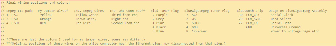
the 8 way Molex 'tuner' connector is wired as follows:

1 - Pink - level
2 - Grey - signal
3 - Blue - Power Ant (not connected on wiring harness)
4 - Black - 0v (ground)
5 - Brown - TX (from tuner)
6 - Red - RX
7 - Purple - no connection (not used in PCATS tuner nor in factory tuner)
8 - Blue - 12v
Supplying power to the external circuit from the tuner plug connection (through a 5v power supply of course) works fine. The amount of noise is unchanged, but I much prefer the idea of my assembly connecting to this existing connector instead of trying to manage additional power connectors, so I'm going to roll forward with that. Thanks!
Okay, I might pursue using the Tuner serial port for the BT module connection then. This way would leave the empeg's primary serial port available for the usual troubleshooting etc. without any conflicts or special handling needed.
The Tuner port is (I believe) 5V TTL logic, which will need to be voltage adapted for the 3.3V CMOS on the BT module. I expect just a couple of resistors will do the trick, but will find out when I do it here.
The noise is pretty faint so it's hard to be sure. It's at the level where you can't hear it unless the song has a really long faint fade-out.
The BlueGiga's ADC seems to have a "floor" or a "noise gate" where extremely quiet sounds don't get sent to the ADC at all and there's just digital silence. So for example, songs with long fade-ins or long fade-outs might have a very small bit of the quietest part of the fade cut off. The amount of noise I'm hearing is just barely on the edge of that noise gate's sensitivity level, so what I get is an intermittent thing where occasionally I hear a faint bit of noise floor appear for a second or so, then it drops below the sensitivity threshold of the noise gate then it fades out again. It's only audible if I turn up the volume on the head unit really loud. But my goal is to eliminate it completely so that even that's not a problem.
Side note: I've also looked through the commandset looing for a way to bring that noise gate's threshold setting down even further, so that it doesn't cut off even the quietest fadeouts. But I can't find any command to adjust the threshold of that noise gate. I'm already controlling the gain and the preamps and the mic bias voltage, and those are set correctly in my code, I can't find any other settings related to that.
I'm using an SSD so I can't tell if it's spinup/spindown related.
I haven't tried switching back to the 7805, I'm going to try switching forward to that isolated voltage converter instead, it comes in the mail tomorrow. If that doesn't solve the issue, I'll try comparing the three power supply types.
This implements the proper responses to the head unit's queries for track metadata, in cases where it attempts to query for multiple pieces of metadata in the same query line.
I haven't gotten a chance to see if this fixes the problem with my roommate's Kenwood stereo yet. Crossing my fingers!
The noise is pretty faint so it's hard to be sure. It's at the level where you can't hear it unless the song has a really long faint fade-out.
Rush, "Red Barchetta"?
Play the track on some other device to be sure the problem isn't in the track itself, and experiment with different tracks as well. I suspct you have already done those things, but that's the limit of my technical competence so is the only suggestion I can make.
Thanks for that suggestion. Unfortunately its not that simple. Im using a large variety of tracks to test this, and I also have the ability to A/B with other playback systems and also with the pure digital versions via A2DP with my phone, so Im certain I know the difference between noise floor extant in the track and noise added by external electronics.
I got the new isolated power supply and hooked it up and tried it out.
It seemed to work but it made a faint humming/whining noise during operation. Not noise in the audio chain, but I mean physical noise when I put me ear up next to it. I've heard power supplies that whine a bit before, so I thought maybe this was normal operation and kept trying it out.
The ground loop noise on the bluetooth/arduino/empeg assembly audio chain was even less than with previous power supplies. Not 100 percent gone, but definitely much much better. Prior versions of the noise were a combinaion of an electronic hum as well as a rushing-wind kind of static noise floor, but with the new power supply it was only the static noise floor, and that was pretty quiet.
Unfortunately I noticed that the bluetooth and arduino were a bit unstable, as if maybe it wasn't supplying the right voltage. Example of what I mean by "unstable" is that the bluetooth connection would drop occasionally, or the reset button that I implemented on the arduino would not function sometimes.
So I unplugged the new power supply and went back to the pololu power supply. And then I plugged in my USB debug cable into the Arudino to work on the programming side of things and... nothing. Nothing comes out on the debug cable.
What's interesting is that things go IN on the debug cable just fine. And the communication between the arduino and the bluetooth board are fine. I know this because of the behaviors I have programmed into my code. I can press the reset button and my blue LED connected to the arduino lights up and it erases the bluetooth pairing on the bluetooth chip, exactly as it is supposed to. I can do all the actions that I normally can do and they all work. I just don't see their output logs on my arduino serial debug monitor any more.
I can SEND commands to the bluetooth module by typing them into the arduino debug console and they get there, they arrive and do the correct thing. For instance if I type BOOT 0 into the arudino debug console then the bluetooth chip correctly reboots (it disconnects form whatever it was paired with and then reconnects after a moment). So SENDING text to the Arduino works.
But I don't see any serial ooutput coming BACK from the arudino. And I know that my program outputs stuff back (regardless of echo on or echo off), it's got specific logging commands that my program has said to put there, and those commands are in there pretty constantly from power-on. For instance, I can press my reset button and my blue LED lights up to indicate it's in paring mode, and I know at that moment I'm echoing a bunch of messages to the arduino debug serial port, but I'm not seeing them on the console.
I tried reloading a program onto the arduino, it times out because it can't get a serial signal back saying that it is receiving the code.
I tried fully unplugging the arduino from the entire assembly and connecting it solely to the computer just from the USB cable. Same thing.
I tried plugging it into an entirely different computer and different operating system (going from Mac to Windows), which entailed installing the arudino development software and device drivers from scratch on the new computer, same thing.
It's not a baud rate thing, because (a) the program sets the baud rate and I know the program is working, and (b) I tried different baud rates on the monitor anyway. Same thing.
Wow this is weird. I don't see how the new power supply could have done this to the arduino but I suppose it could? I don't know. Why would it fry only one direction of the arduino serial port while the rest of the thing works perfectly for everything else? Weird.
This makes it so that the same set of notification commands is always sent to the bluetooth chip every time a track changes or the playback status changes. This was an attempt to fix the bug with the Kenwood headunit where it only ever got the first track title on its screen and never got subsequent ones.
It didn't fix that bug, but it fixed another previously-unmentioned bug where I had a bluetooth headset which wasn't successfully pausing/unpausing when I pressed its pause button. Something about the change in the last set of code fixed that bug, and now the headset correctly pauses and unpauses.
Here's what was going on with the Kenwood bug (from my code comments in the update above):
// Final fix for the "Kenwood Bug". Description of the Kenwood Bug: // The AVRCP NFY CHANGED commands work on factory car stereo in // Honda Accord 2017 model no matter what the transaction label is. // This led me to believe that the transaction label was only important // when performing an immediate response to a state query (i.e., when // sending an "AVRCP NFY INTERIM" response), and that if I was the one // who was indicating the state change (i.e., when I was sending an // "AVRCP NFY CHANGED" statement to tell the host that something had // changed), that the transaction label was arbitrary and that I was // the person choosing the transaction label at that time. This was // fine for the Honda stereo: When those commands are issued to the // bluetooth chip, then the car stereo head unit immediately reacts // by re-querying for more new track metadata from the bluetooth chip. // // However, when using those commands on a Kenwood bluetooth-equipped // car stereo, then nothing happens when the messages are sent up // with arbitrary transaction labels. The Kenwood stops sending new // queries for track information and just "sits there" blindly // playing the audio stream without getting any new track data. // // It turns out that the transaction labels aren't arbitrary if // you received a "REGISTER_NOTIFICATION" message for the // "PLAYBACK_STATUS_CHANGED" or the "TRACK_CHANGED" messages. // Yes, you need to immediately respond with an "INTERIM" // notification, but then if you send a "CHANGED" notification // yourself later, then the transaction label still has to match. // The Kenwood stopped querying for new track data because the // transaction labels didn't match when I sent it "CHANGED" // notifications. The fix is to match the transaction labels // by storing them in a global variable.
As far as the noise goes, I think I'm going to attempt to make a first pass at a PCB and see if all I really need to eliminate the noise is to simply get things more solid with better ground traces and everything, instead of jerry rigged on a breadboard.
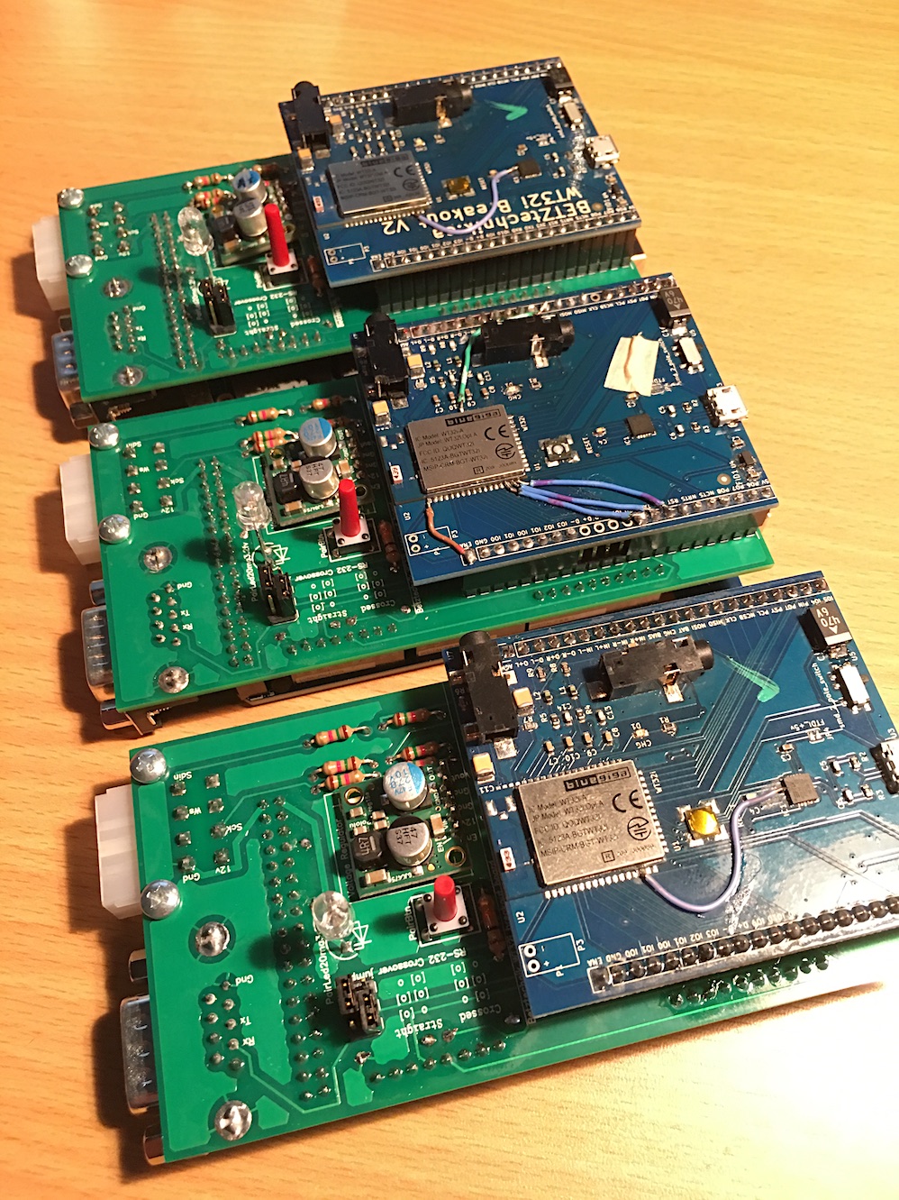
Now that the software and my breadboard prototype are working well, I've just ordered a PCB from Pad2Pad. Should have a video of the assembled version of that in the next 10 days or so.
- I have a working car installation, with the breadboard prototype and the attached empeg velcroed to the floor of my trunk, Eutronix remote display extender is installed and working in the sunglasses holder in the ceiling up front. Works well and sound is good.
- I have a PCB on the way from Pad2Pad that should allow me to turn the prototype into a single nice little box that I can mount better and well protected in the trunk, while still allowing me to pull out the player and dock it to load tunes indoors.
- There is a bug in the software, such that high-ascii characters are displayed as an inverted question mark on the car stereo screen. So Béla Fleck and Blue Öyster Cult look funny, for example. Will work on fixing that soon.
Questions for Mark Lord and Stu:
Stu's digital interface does I2S, and its instructions seem to show some simple I2S connection pads on the empeg motherboard. There are some I2S pins on the BlueGiga development board, and there are instructions in the BlueGiga docs which say how to route the audio from the I2S pins (you have to issue a particular couple of commands to the BlueGiga chip).
Question 1: Is it as simple as a couple of wires to connect the I2S on the empeg motherboard to the I2S pins on the BlueGiga board? Or is some buffer circuitry needed or what?
Question 2: If I am getting my audio from I2s instead of from the audio out jacks, what features will be lost if any? Or will these all work as expected even through I2S? - Left right time alignment? - EQ? - Bass/treble boost? - Auto volume adjust? - Volume control from front panel?
The I2S pads come more or less directly from the empeg's DSP chip, so that would be AFTER pretty much everything has been done to the audio. I haven't tried it yet, but all of the adjustments should "just work" through I2S.
However.. it is not entirely clear to me whether the I2S outputs use 5V or 3.3V. The datasheet for the DSP seems to indicate 3.3V, but I'd like to see it on an Oscilloscope just to confirm. Stu would already know this too, so if he chimes in..
EDIT: The schematic indicates 3V on the IIS header, so it should be good.
That's important, because 5V could fry the BT module. So you really want 3.3V logic there. Easy to convert 5V to 3.3V with a 10Kohm and 20Kohm resistor ladder, if it is needed.
So should we try it with just some wires? Do we know what the pinouts are for that header? Stu's instructions also have a connection to a timing crystal, would that be needed as well?
I don't know what Stu needed the connection from the side of that crystal for. No schematic of Stu's device here, so you'll have to ask him what that was all about.
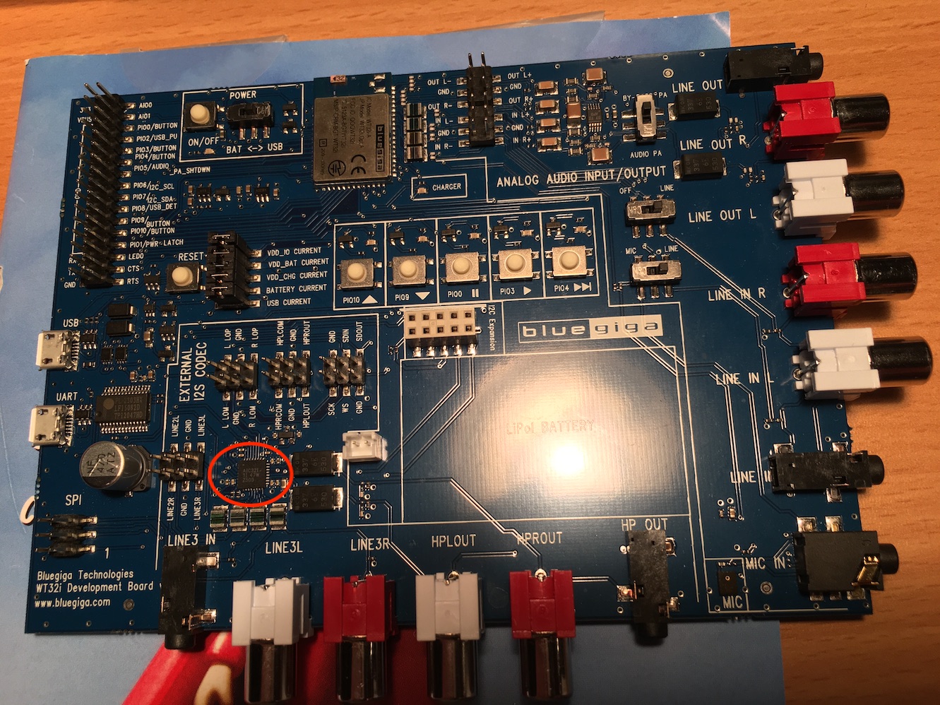
But here is the layout of the I2S (aka. IIS) header inside the Mk2a, along with the nearby 3V power source.
Stu appears to be using IISC, IISW, and IISD1 from the header. Ground is also available there, so no need to go hunting elsewhere for it. Those are the same pins we'll want to connect to header J12 on the BT dev board (SCK, WS, SDIN, GND).
Wow that looks really straightforward. Thanks! Maybe I'll get a chance to try it later this week or this weekend. If you try it first, let me know!
According to the docs, you have to issue these commands to get the dev board to route from the I2S connector:
SET CONTROL AUDIO INTERNAL I2S EVENT 32 SET CONTROL EXTCODEC PRE 30 18 0200918000008A1037000100008000000FF07C7C787C7C78 30 04 25C01400 30 0a 28C00000000000008000 30 03 330F00 30 05 3F00800F00 30 04 6500A200 RESET
In the meantime, I'm having a devil of a time trying to find out how to get high-ASCII characters to appear on the car stereo screen. I can't find the bluetooth specification information for how to handle non-ASCII characters in the strings sent up in the AVRCP metadata.
Hm, I misread those commands in the docs. The "EXTCODEC" command is for setting up an external TI codec included on the dev board. I think that perhaps you might only need the first command to use the empeg I2S:
SET CONTROL AUDIO INTERNAL I2S EVENT 32
And mayyyybe a "RESET" after that. Might be that simple.
Also the number might not be 32. The docs say "...configures I2S to use 32 bits per sample to suit the clocking requirements of the TI codec" so I don't know if the empeg needs that or if it needs 16 in that slot or what.
- Adds an aggressive reconnection retry so that once you've paired up with your car stereo, then after that, each time you start your car, the empeg tends to be the device that connects to the car stereo first, rather than playing tunes from the phone in your pocket. On my car now, when I start it, it connects the music to the empeg and the phone/voice to my cell phone. Nice.
- Fixes the issue with High ASCII characters in track titles by converting high ASCII to UTF-8 before sending it up the bluetooth link. Works well, now my Blue Öyster Cult and Béla Fleck tracks look correct.
Last night, my friend Fishy used his expensive high tech mill machine to clean up the edge cuts on the sunglasses holder where I mount the remote display. I'm really pleased with the way it's looking so far. I should also hopefully receive my PCB from Pad2Pad and I should be able to solder up a much better attachment box without having to use the breadboard. If I get that all working I'll post another demo video with everything in place.
Regarding the I2S connection on the Empeg motherboard - Would you expect that the GND for that is the same as the GND for 12V on the tuner connector?
I'm thinking of hijacking more wires on the tuner connector to run I2S out the back of the sled (disconnecting all existing tuner connector wires from the empeg motherboard except for the 12v power and ground).
Since the IIS header on the empeg motherboard is not labeled, I'm going by your earlier post regarding the pinouts of the IIS header, and the photo of the connected wires from Stu's digital interface installation instructions.
Yellow wire in Stu's instructions: Assumed to be PL8 - Pin 1 - IISC Orange wire in Stu's instructions: Assumed to be PL8 - Pin 2 - IISW Not connected in Stu's instructions: Assumed to be PL8 - Pin 4 - GND - (I have added a blue wire here). Red wire in Stu's instructions: Assumed to be PL8 - Pin 4 - IISD1 Not connected in Stu's instructions: Assumed to be PL8 - Pin 5 - IISD2
I am connecting (based on the assumptions above and your earlier post):
Yellow wire connected to BlueGiga board SCK pin. Orange wire connected to BlueGiga board WS pin. Blue wire connected to BlueGiga board GND pin. Red wire connected to BlueGiga board SDIN pin.
Note: Don't usually need that blue wire except when I've got everything split out on the workbench and the empeg and the bluetooth module are getting their power and ground from two different places.
The final version of the secret command you have to issue to the BlueGiga module to make it work turns out to be:
Code:
SET CONTROL AUDIO INTERNAL I2S_SLAVE EVENT KEEPALIVE 16
And at some point in my setup code, the device eventually gets this command: RESET
The format of the command, according the iWrap 6 command reference, is:
SET CONTROL AUDIO - The preamble for the command INTERNAL I2S_SLAVE - The input and output audio routing. It doesn't seem to matter what I set the first one to, as long as the second one is set to "I2S_SLAVE" because that's the one we're using in A2DP "Source" mode. The other one is unused by our configuration. EVENT - To receive audio routing events. KEEPALIVE - Prevents DSP from powering down between A2DP streams. Removes possible clicks and pops from the beginning of the analog audio stream. Might decrease also A2DP latency. Increases power consumption when not streaming audio. 16 - Unused since we are in slave mode, it specifies the number of bits per sample when using I2S master mode. Can be 16/20/24/32 (default 24). I'm stuffing a 16 in here just for something to put in there.
Stu's instructions say something about how the audio volume on the empeg might need to be set to one notch down from 0db to keep the audio from clipping. I'm going to experiment with that.
I think you should really go for using the Tuner's serial port too, instead of the primary empeg serial port. Just two pins on the tuner connector (RX,TX), plus (exising GND).
The RX (to tuner/BT-module) pin requires a resistor ladder to step down the voltage from 5V to 3V logic. the TX (from tuner/BT to empeg) can connect without modification.
The resistor ladder on RX should consist of a setup like this:
Connect the RX (BT module) to the (+)point in between the 10K/20K resistors. No MAX rs232 chip required.
The two resistors function as a voltage divider, converting the 5V RX output from the empeg into (20/(10+20) * 5.0V == 3.3V) suitable voltage to not fry the BT-module.
EDIT: Oh, I keep forgetting you have the Arduino in-between right now..
Thanks! Maybe someday I will indeed try to do it sans Arduino and get it working fully internal to the player. But now that I have it working as an external box with all the features I want, I'm going to refine this for now and finalize the current design. In the meantime I'll give you any support you need for doing the internal version yourself.
Here's my thinking at the moment...
If anyone besides you or me ever wants one of these for themselves, then they can have three different ways of doing it:
1. Fully external box which requires no player modifications, uses analog audio plugs. Requires an Arduino and one of the WT32i dev kit boards.
2. External box like 1 above, which can also work with digital I2S connection, but you have to be willing to open up the empeg and solder to the I2S pads and hijack some wires out the back of the docking connector (I'm currently using three of the tuner module wires successfully for this).
3. Fully internal to the player, using the tuner serial lines for command/control of the bluetooth and the I2S pins for the audio, but requires additional connections and soldering internal to the player, and takes up a drive bay slot for the assembly.
I currently have a working implementation for either/both Way 1 and Way 2, and I'm designing my second revision of the printed circuit board already. Once I get that second PCB made and tested, I could be set up for manufacturing these things as complete modules, or selling them as kits. The second revision of the PCB will allow the module to be used in either Way 1 or Way 2.
For way 3, I think that you should totally run with that. You know so much more about programming for the Empeg and you know so much more about EE than I do, I think you'll be totally successful at that. Your version would be smaller, simpler, and MUCH cheaper to manufacture.
I'm pretty excited about this. I know the software is going to need a lot of tweaking though, so there will still be updates to the example code. If anyone else wants one of these, I'll bet that it won't pair up perfectly with their stereo and will need additional code tweaks. Each time I try this thing on a different bluetooth device, I discover some other little thing that doesn't work and I have to update the code again.
Still, having a lot of fun (and stress) with this project. I've been through so many twists and turns with the circuitry, most of which I haven't mentioned on here. Last couple of days it was weird thing with the serial connection failing on the PCB from Pad2Pad which turned out to be just traces grounding out when they weren't supposed to be, and I had to jumper around some shit. Next design from Pad2Pad will have bigger clearance around the traces than their recommended settings. Live and learn.
I'm super grateful for you and for the other folks on this BBS for the suggestions and the help. The initial idea for doing this was from two people: FieroSTI for having made a bluetooth input board for the empeg (the opposite thing of what I'm doing now), and Elperepat for pointing out the original BC127 breakout board at Sparkfun.com. From there it just snowballed. You all have been super helpful with all sorts of great suggestions related to the bluetooth stuff and for the electrical circuits. It's just been amazing. Thanks all!
I am not likely to "manufacture" anything for this. My plan is just to get my own setup going (after Christmas), and share whatever it takes to do so.
The first rev will be the external BT dev board, connecting to the tuner connector on the empeg, most likely with I2S also hooked up through the tuner connector. The empeg CPU will do all of the control etc..
If I ever do a second rev, it will be to replace the large/expensive BT dev board with just the BT module instead, and that is tiny enough to be mounted inside the empeg (probably in a drive bay). I had been shying away from doing this, because of the difficulty (for me) of keeping clean audio paths. But with pure digital audio interconnects (I2S), that all becomes a non-factor. Thanks again, Tony!
When your code uses the tuner internal serial port, it'll be accessing to the RX/TX lines internally on the empeg, correct? So you don't need those RX/TX pins to be connected externally on the tuner connector out the back of the sled, correct? So you could do like I did and disconnect those pins from the wiring header that connects them to the sled harness inside the empeg and then those can be used for running some of the I2S pins out the back of the tuner connector, like I did. Right?
If we use the same pinouts on the tuner connector, then both of our designs will be compatible. Would that work for you?
Here's the pinouts I'm using on the 8-pin molex tuner connector. Let me know if these work for you. Note that the colors listed are the externally visible wire colors on the tuner connector outside the player. The colors are different on the internal wiring header that connects to the motherboard.
1 - Pink - originally "tuner level", now disconnected from internal wiring header inside the empeg and soldered to a jumper wire which is solodered to I2S pin "IISD1" inside the empeg. This is pin 4 of the IIS header on the empeg motherboard, the 4th pin from the "notch" on the silkscreen outline. On my external board, this is connected to the SDIN pin of the BlueGiga module.
2 - Grey - tuner signal - left unchanged - No connection on my external board
3 - Blue - Power Ant - left unchanged - No connection on my external board
4 - Black - Empeg Ground - Connected to the ground on my external board, which is connected to several ground pins in various places on the BlueGiga board and the Arduino board. In particular it's connected to the GND pins on the I2S header on the BlueGiga board.
5 - Brown - originally TX, now disconnected from internal wiring header inside the empeg and soldered to a jumper wire which is soldered to I2S pin "IISW" inside the empeg. This is pin 2 of the IIS header on the empeg motherboard, the 2nd pin from the "notch" on the silkscreen outline. On my external board, this is connected to the WS pin of the BlueGiga module.
6 - Red - originally RX, now disconnected from internal wiring header inside the empeg and soldered to a jumper wire which is soldered to I2S pin "IISC" inside the empeg. This is pin 1 of the IIS header on the empeg motherboard, the pin next to the "notch" on the silkscreen outline. On my external board, this is connected to the SCK pin of the BlueGiga module.
7 - Purple - unused - left unchanged - no connection on my external board.
8 - Blue - 12v - Connected to my 12v input on my power supply regulator on my external board.
For the dev board, the TX/RX pins on the tuner connector will be needed. So let's leave those intact. Also, the empeg has 5V available internally, so if we feed that out the tuner connector, then there's no need for any extra voltage conversions.
Code:
1 - Pink - level
2 - Grey - signal
3 - Blue - Power Ant (not connected on wiring harness)
4 - Black - 0v
5 - Brown - TX (from tuner)
6 - Red - RX
7 - Purple - no connection (not used in PCATS tuner nor in factory tuner)
8 - Blue - 12v
So, referencing the above, pins 1,2,3,7 are all available for our use. We should keep 4 (GND), 5(TX from tuner), and 5(RX to tuner).
There are enough leftover pins to use one of the remaining pins for +5V in addition to keeping +12V, and still have three pins for I2S (SCK,WS,SDIN).
So, how about you decide the final assignments within those constraints? If for some reason we end up needing another pin, then we could put +5V in place of the +12V on pin 8.
In the meantime I have another code update with some more bug fixes and minor behavioral changes. I'm trying to get the initial boot-up and connection procedures to behave as cleanly and quickly as possible.
Once you guys get all the wrinkles worked out, I will definitely be doing this. I'm not in any hurry, but at some point in the next 18 months or so I'll be in the market for a vehicle and would love to have the empeg running again (right now we only have the one minivan and I've been warned not to fool around with the built-in DVD system). Until then, I'll be lurking and collecting parts and having them brought down to Mexico. I've just been waiting to purchase until Tony found a board that was actually viable.
I also travel quite a bit when in the US as I visit churches all over the country. It would be great to have an empeg that I could just carry into a rental car, plug into the lighter and connect via bluetooth (ie...the fully internal option above).
Cool. We'll have the kinks worked out soon and hopefully make it into a very simple kit. :-)
An example of a kink that I have to work out (well, a bug in the empeg player that I must work around) that I just discovered:
N serial_notify_thread.cpp: 116:@@ N10 serial_notify_thread.cpp: 117:@@ F0xf8b0 serial_notify_thread.cpp: 118:@@ TAquafin serial_notify_thread.cpp: 119:@@ ATony Levin serial_notify_thread.cpp: 120:@@ GInstrumental Rock
N serial_notify_thread.cpp: 116:@@ N11 serial_notify_thread.cpp: 117:@@ F0x10640 serial_notify_thread.cpp: 118:@@ TWhere the Streets Have No Name serial_notify_thread.cpp: 119:@@ AU2 serial_notify_thread.@@ GRock
And now it's not reproducing consistently. It reproduced perfectly before (only on the U2 track and not any of the others) and now it's not reproducing and... GRRR.
Wait, no, now It's sometimes reproducing differently. Now I see it like this:
N serial_notify_thread.cpp: 116:@@ N11 serial_notify_thread.cpp: 117:@@ F0x10640 serial_notify_thread.cpp: 118:@@ TWhere the Streets Have No Name serial_notify_thread.cpp: 119:@@ AU2 serial_notify_thread.: 120:@@ GRock
Now I'm starting to suspect my own code even though the examples above are straight character-in-character-out on the serial port.... More research is needed...
So, what I see there is that it sometimes drops the "cpp" part of the string? That part alone is easy enough to ignore and deal with.
Oh, okay.. second example dropped a few more chars. Really looks like it ought to be the receiver (Arduino) at fault, but I suppose it could be a buffer overrun on the empeg TX path too.
I do seem to recall having to fix the Arduino library here for one of my projects: it had WAY too small of a serial RX buffer for my needs. Increased the buffer size, and problems went away.
I was already sure it wasn't a serial buffer problem because my code handles single characters in and out in a fast loop, and my repro was only on that one U2 song going back and forth across it. But that tip is really useful and I will keep that in mind just in case I need it later.
I have traced it down to memory overwrite problems in the Arduino program's string handling which surrounds the processing of of track metadata. To make the bug go away, I can either skip the UTF-8 conversion step, or I can skip the logging that says "Artist changed to xxxx", either way the bug disappears. So it's some sort of bug related to the way those strings are handled. I'm going to poke at it some more and get the code updated to fix the bug.
I spent this afternoon writing a script to convert (most of) the Arduino C++ sketch into plain POSIX C, in preparation for trying to run it on a Linux laptop or empeg. The idea is that I just re-run the script with minor mods whenever you update the sketch.
Still poking away at it, but perhaps 75% of the way there now. The variable numbers of arguments for things like .substring and the like are giving me the most grief.
There are updates to the sketch today but I'm still kind of in-process on parts of it.
Then today, the BlueGiga dev board flat out stopped working. It's like it's not getting any power or something any more. And I tried it bare with just its USB cable into the UART port which used to work, but now it doesn't. I don't see any burned out components on the thing. Some time perhaps tomorrow night I'll start looking for things like bad solder joints.
It could well be (1) running too low on RAM, or (2) running out of stack space (too many nested calls, too many local variables).
Indeed, I have had that happen before in Arduino sketches. But why it would hit that condition only on that U2 album is weird. I think there's a pointer bug in some of the String functions in their compiler, and it was only triggered because the Artist string was only two characters long. I'll look through and see if it happens for other bands on my empeg which have two-character artist names. I think there might be a few of those to try, or I could edit a tag on a test song.
Quote:
Using String types instead of char * for strings results in lots of added memory usage and overhead. Arduinos don't have much to burn.
Totally understood, but the reason I was trying to use the String type was precisely because I didn't trust myself not to create memory-overwrite bugs when using char*. Literally the thing that happened was specifically the thing I was trying to avoid. Is that Morissetian irony, or just plain irony?
So, how about you decide the final assignments within those constraints?
When I get the bluetooth dev board working again, I will try to go with this (jury is still out until I actually implement it for sure though):
Code:
1 - Pink - Originally level - Now IISD1 (empeg) <-> SDIN (bluetooth)
2 - Grey - Orignially signal - Now IISW (empeg) <-> WS (bluetooth)
3 - Blue - Power Ant (not connected on wiring harness)
4 - Black - 0v (unchanged)
5 - Brown - TX (unchanged)
6 - Red - RX (unchanged)
7 - Purple - Orginally no connection - Now IISC (empeg) <-> SCK (bluetooth)
8 - Blue - 12v (unchanged)
Quote:
Also, the empeg has 5V available internally, so if we feed that out the tuner connector, then there's no need for any extra voltage conversions.
But since I'm still leaving 12v, ground, TX, and RX unchanged, that leaves only one wire left for that 5V run:
Code:
3 - Blue - Power Ant (not connected on wiring harness)
... And that one isn't connected to the wiring harness. There's no pin on the docking connector for it. And I can't hijack the existing 12v blue wire because that's the one that comes out the dock connector for the Amp Remote wire. So I think we're stuck with our own power supply.
I spent this afternoon writing a script to convert (most of) the Arduino C++ sketch into plain POSIX C,
By the way, I've done that sort of thing with the Roslyn library features, converting an entire company code base of Nunit 2.x and MSTest unit test cases into Nunit 3. It was painful but I did it!
There's no pin on the docking connector for it. And I can't hijack the existing 12v blue wire because that's the one that comes out the dock connector for the Amp Remote wire. So I think we're stuck with our own power supply.
I was wondering about stuff like that. Okay, so let's steal something else from the main docking connector? The microphone, perhaps? Or one of the main serial port pins (since they're all on the back of the case as well as on the docking connector). DCD perhaps?
Or one of the main serial port pins (since they're all on the back of the case as well as on the docking connector). DCD perhaps?
Nope, only RX and TX and Gnd are connected to the serial port plug, and it would be a bad idea to get rid of those, a worse idea than getting rid of the tuner module serial connector. There are some things you can only do on the player if you've got that main serial port available. I personally know that I wouldn't give it up on my player.
There are a couple other pins coming out of that part of the serial connector, but they're being used for Cell Phone mute and Headlight Dimmer Sense instead of things like DCD and such.
Oh hey. Cell phone mute might be good for that. I think I already talked about that wire earlier. Since we're doing a bluetooth project that connects to a head unit that will have cell phone mute inherent in the bluetooth connection, a physical wire is no longer needed for that.
So are you suggesting to get another male pin for the empty one on the Molex tuner plug, and wire the docking connector pin which USED to be the cellphone mute wire and then adding that to the tuner connector instead, and then make that the 5v supply? That seems like a lot of surgery to go to just so that we don't have to build a power supply into our design. I think it's better if we just bite the bullet, do the power supply, and simplify the connector down to just that one tuner plug and three wire modifications inside the empeg. That Pololu supply I got is working fine and is super easy to wire up.
Yeah, okay. Simple enough to just use the existing 12V for power.
I just find it a bit weird to be going through so many contortions to get voltages that already exist in fine form from the empeg.
The BT module REALLY wants 3.3V. But it doesn't have a suitable input on the dev board for that. So we feed it 5V, and it has an onboard power supply to make that into what it wants: 3.3V. The empeg has both of those available, but instead we're feeding it 12V. Just seems peculiar, though convenient.
But yeah, let's have just one voltage out for now, and the existing 12V is probably it.
I didn't realize that the tuner molex has only 7/8 pins populated -- I have replacement connectors for it here, so mine have all 8 pins. Perhaps I'll use the "spare" unpopulated pin for my own purposes..
I didn't realize that the tuner molex has only 7/8 pins populated -- I have replacement connectors for it here, so mine have all 8 pins. Perhaps I'll use the "spare" unpopulated pin for my own purposes..
The problem isn't the missing pin on the molex connector, the problem is that there's no corresponding position coming out of the sled docking connector for that spot. So it's more than just "not populated", it's literally not available at all for connecting the inside of the player to the outside world. So you'll have to hijack a different wire from somewhere else on the docking connector for that purpose. The cell phone mute wire is a great candidate for that, I think, it just requires more complicated surgery.
Found another copy of the sled wiring diagram in the BBS history to help illustrate. It shows the cell phone mute wire as a light green wire that is connected to serial plug pin 1, and the headlight illumination sensing wire as a gray wire (actually white in reality) connected to serial plug pin 8.
I think my BlueGiga dev board started malfunctioning in terms of its internal power conversions circuits yesterday.
It stopped working entirely, and I got no output from its serial ports.
Tonight I measured the voltage on several of its pins, and I did this measuring both with it hooked into my assembly and getting its voltage from there, and also when it was disconnected from my assembly and getting its voltage directly from the serial port. For places where it was supposed to be getting 3 volts, such as "VDD_IO" it was only getting 1.5 volts. And for places where it was supposed to be getting 5 volts, such as "VDD_CHG" it was only getting 4.5 volts. All other voltage test points were similarly lower than expected.
I verified that my assembly was putting out exactly the expected voltages: 4.95-5.00v on the 5v pins.
However when I connect my assembly to the BlueGiga board, the voltage on those pins drops to 4.5v.
If I take the 3v pin from the Arduino and jumper it to the 3v pin on the BlueGiga board, then suddenly it all works again. I wasn't using that pin because I had previously been using the 5v input ("VBUS") pin on the BlueGiga board. Do you think I should change that so that I use the 3V pin coming out from the Arduino exclusively instead? Or maybe both Vbus (5v) and 3v simultaneously (since Arduino outputs both)?
I think the chip seems to work correctly whether I connect the 5V rail or the 3v rail either way. Can you tell if there's anything on that dev board that truly needs the 5 volts besides the battery charger (that we're not using)?
Hm. When I connect that 3V rail and the board is working again (regardless of whether I have the 5v rail connected, then this chip on the BlueGiga board gets quite hot.
This occurs without any of the I2S pins connected. All that's connected are jumper wires from the Ardunio on these pins: - 5v (either connected or not) - 3v - Gnd - RX - TX
This worries me. What has gone wrong with my BlueGiga board I wonder?
And I wonder if that chip or any of its supporting circuitry is the problem and if I can disable it easily?
When I connect up the board with just the 5v rail connected, the chip doesn't get hot, but also the BlueGiga doesn't work and I get no serial output from it.
Whereas if I connect up the board with the 3v rail connected, the BlueGiga works and I see serial output, but the AIC32I audio codec chip gets real hot and I'm afraid to leave it that way for any length of time.
This is with all I2s connections disconnected by the way. Just the power, ground, serial.
And even when I briefly supply the 3v rail to get the board working again and pair it up with a bluetooth device, I no longer get the I2S audio out any more.
I think that circuit is fried. I sure wish I knew whether it was something I did or if it was just a bad chip or something else bad on the dev board.
Mark, how tough do you think it would be to do the WT32i chip bare, without the dev board? How much supporting circuitry do you think we need for: - Serial RX/TX - Line in - I2S in.
Even willing to drop the line in at this point, even though my whole idea was a fully external box so that folks don't have to mod the inside of their empeg.
Attached is a screen shot of the relevant portion of the schematic of the WT32i development board where they have that external codec plugged in. It's part of their zip file of the full design documents for the development board at this link: https://www.silabs.com/documents/login/reference-designs/DKWT32i-v2.2.zip
I wonder if I have blown one of the caps in that ladder that connects to its power inputs. I don't see anything visibly physically wrong, everything looks OK there.
I do seem to recall having to fix the Arduino library here for one of my projects: it had WAY too small of a serial RX buffer for my needs. Increased the buffer size, and problems went away.
Look for "#define SERIAL_BUFFER_SIZE" and make it bigger.
I thought I'd try this, even though I had convinced myself it wasn't the root of the issue, I'm having trouble locating the root of the issue so I'm going back over my previous assumptions and I'd like to try this. My problem is that I can't find the file in question. I'm doing the development on Mac OS X and the file just isn't showing up anywhere that I look for it.
Searching for this information on Google isn't giving me any valid answers, unfortunately.
I found the file - Macs have something that looks like a single application file (in this case "Arduino") but it's actually like a zip file. The USBAPI.h was in there. I am not 100 percent certain that I edited it correctly or that the compiler will "take" the file or not, but I tried it.
I think the best place to connect external 3.3V power to the BT-dev board would be at the (white, 2-pin) battery connector (or to the "Battery Current" jumper). That input will accept up to 4.4V, and it gets internally regulated to what the various parts of the dev board want.
Connecting it directly to the 3.3V (OUTPUT) on the top-left header isn't ideal, and could be why parts of the board want to overheat.
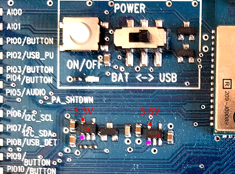
Now, why the external USB power wasn't working: this should just be due to the 5V-to-3.3V conversion chips perhaps having failed. There are two chips in series for this: U14, and then U1 (labelled photo attached).
U14 (on the right) converts the 5V from USB down to 3.6V ("battery level"). U1 (on the left) converts the 3.6V from U14 down to 3.3V ("logic level").
You can check for correct operation of each of those with a voltmeter. Power the board from the USB connector (or possibly the UART connector, but I'm using the USB connector here).
The top left pin of each chip is its output. Measure voltages using either of the USB shells as GND. The chip on the left (U1) should be outputting 3.3V, and the chip on the right (U14) should show 3.6V.
If either chip doesn't show the correct output, then check the input to each chip, on the bottom left pin (magenta dots in the photo).
Did some continuity testing, and the SCK pin on the BlueGiga chip has continuity with the 3v rail. Maybe that's the root of it.
From reading the datasheet, it appears that SCK (and SWS) are bidirectional. The Wt32i can be programmed to have those as inputs (what we need), or as outputs. If the latter, then you'll see 3.3V on them (bad).
I like the look of that. Cheap-ish at only USD$10+shipping (without WT32i). And it takes care of converting the pin spacings to something more usable for us. Ordered one!
If you look at the schematic for it, it shows what extra circuitry is needed to run a standalone wt32i: not much, just a 5V to 3.3V power supply, and it also provides a USB-UART for easy programming. That, with a WT32i module on it, looks darned near perfect for our needs when using I2S.
I am not 100 percent certain that I edited it correctly or that the compiler will "take" the file or not, but I tried it.
I changed it to 256 but it didn't fix the issue.
There were two lines with that setting in mine here, with an #ifdef deciding which one to use. You can test whether or not your mod gets picked up by inserting a #error line there for testing. Eg.
There were two lines with that setting in mine here, with an #ifdef deciding which one to use.You can test whether or not your mod gets picked up by inserting a #error line there for testing. Eg. #error "it works"
Mark, you are brilliant, thank you. My change isn't getting picked up.
I inserted the #error "it works" , both with and without the quotes (the file has an example of it without the quotes right below there) and tried putting it both before and after some of the #if statements surrounding the SERIAL_BUFFER_SIZE stuff in that section of the code (including placing it before the #ifndef SERIAL_BUFFER_SIZE statement so it should definitely have been hit). The compilation step never blows up with an error message, either when using the installed local Arduino compiler or their online compiler.
So if my issue really is a serial buffer size issue, then this change isn't helping because it's never hitting the change. That's so awesome that you suggested putting an error into the compilation to see if it even hits the code. Super helpful!
I've been googling around trying to find the correct way to do this, and all the answers say either "make sure your code doesn't ever let the buffer fill up" or they suggest changing the exact same line that you already suggested changing.
If the serial buffer does turn out to be the root of the issue, then I would want to rearchitect the code to fix the issue, but before I do that I need to know if that's even the issue at all, so I want to try to get this buffer size experiment working. I'll keep poking at it.
By the way, the file in question was located in this place on the Mac: Macintosh HD -> /Applications/Arduino (which, once you're inside it, gets listed as "Arduino.app" in the directory tree) (then you have to open the contents of the "Arduino" App, then) Contents/Java/hardware/arduino/avr/cores/arduino/USBAPI.h
When compiling I have tried both the "AVR ISP" programmer option and the "AVRISP Mk II" programmer option, and the compiler output says that at least it's hitting the right folder, though I don't see that particular file in the list:
And of course you were right. The bug goes away if I increase the serial buffer size. I feel terrible for rejecting your suggestion when you first made it.
I have to really rethink some things if I want to work around this issue, or, I could just depend on a bigger buffer. Hm.
My apologies for not specifying the correct file first time around.. I was looking at an older version of the Arduino stuff. Of course in the latest (which I also have and use) it is in the file you found.
The problem you face, is that the empeg bursts a ton of stuff rather quickly on track change. The buffer has to be big enough to hold all of that, or you have to be polling insanely too often.
Bigger buffer is probably best, if you can spare the RAM. This will be a non-issue for me when I do it all internal to the empeg.
Bigger buffer is probably best, if you can spare the RAM. This will be a non-issue for me when I do it all internal to the empeg.
Agreed. I can easily spare the RAM, but I'm trying to make this thing easy for third parties to put together themselves. Editing the Arduino compiler header files (and having to maintain that after Arduino compiler upgrades too) is a pain that I don't want to have to put anyone else through.
But at the moment it's all I've got, for the reasons you cited.
I wish I could just put "#define SERIAL_RX_BUFFER_SIZE 256" into my own code and be done with it, but of course that doesn't work.
I could look and see if rearchitecting my code to use "serialEvent()" works, i.e., if it still calls that routine even if I'm deep inside another routine. In other words, make it truly event-driven instead of polling. I could constantly build up and regularly drain a stack of completed string lines from the Empeg serial port. That might be possible if that function works the way I think it should.
In the meantime, I'm going to put a pre-check step into the Arduino sketch to print a warning message if the buffer size isn't big enough.
And then I will move on to the power supply debugging you suggested earlier - Thanks again so much for that too, that is super helpful.
Track titles are much more reliable now. I fixed multiple bugs that would cause the track titles to sometimes not be parsed properly. Some of those bugs were new String/memory bugs that I induced when I made attempts to work around what I had incorrectly thought were String/memory bugs in the first place.
There is also now the check routine in there to confirm at program startup that the string buffer size is big enough, and will print an error on the serial port if it isn't big enough. Considering whether or not to do something like halt the program and make the LED blink if the string buffer isn't big enough, but I haven't gone that far since the worst thing that could happen is the track titles don't always work.
Yes. That's a weakness in the Arduino library. The buffersize should be a parameter to each instantiation of a Serial object, rather than a hardcoded value that is applied to each and every serial port.
Eg. Right now, if you change that define to 128, this means that all THREE of your serial ports are going to get the same large buffer, wasting a fair bit of precious RAM (on some chips anyway).
But for now, if you can spare 3X whatever the buffer size, then just go with that.
With the smaller WT32i breakout board you found (mine will be here later in the week), I suspect that board will be the one that anyone else here might choose to use. And it is a natural for placement inside the empeg. In which case, the eventual port of the Arduino sketch to native-empeg might end up being what is wanted.
And it will have no such buffer issues, not least because Hijack already captures the notify strings and maintains the latest of each in /proc/empeg_notify for app use.
So probably not worth fussing further over for now, at least. Heck, the Arduino library might even get fixed by the time you need a "simpler" solution. Or you could clone the serial library and distribute a fixed version for installation by others. Or just provide a pre-compiled binary of the sketch. Etc..
U14 (on the right) converts the 5V from USB down to 3.6V ("battery level"). U1 (on the left) converts the 3.6V from U14 down to 3.3V ("logic level"). So, check those and report back.
U14 on the right: 3.54v output on upper left output pin, source voltage on lower left pin: 4.39v U8 on the left: 3.28v output on upper left output pin, source voltage on lower left pin: 3.54v
Additional voltages from the current jumpers in the middle of the board:
3.29v VDD_IO CURRENT 3.54v VDD_BAT CURRENT 1.15v VDD_CHG CURRENT (battery switch is off and no battery is installed) 0.00v BATTERY CURRENT (battery switch is off and no battery is installed) 4.39v USB CURRENT
Something I haven't tried yet... Now that I've removed that TI codec chip, I'm going to see if powering it on its 5v VBUS pin works again.
Indeed it works just fine now, powering from either USB or from my board assembly with the tuner connector, using the 5v "Vbus" pin to power it like I was doing before the malfunction. And now, with that TI codec chip removed, nothing is getting hot any more. I still don't have I2S any more and I have to fall back to analog, though. Which works, but I really miss the cleaner sound that the I2S connection gave me.
I wish I knew which component was the failed one and whether or not I caused it.
I have high hopes for that other breakout board. I ordered one too. Once I get that smaller breakout board, what's your recommendation for which pin to power it from?
I have high hopes for that other breakout board. I ordered one too. Once I get that smaller breakout board, what's your recommendation for which pin to power it from?
There's a contact hole/pin labelled "5V" on a corner of the board at the same end as the USB connector. The schematic shows that pin being connected directly to the 5V contact from the USB mini connector, so that's the one to use.
I wish I knew which component was the failed one and whether or not I caused it.
I am wondering about that external I2S codec chip. If the Wt32i firmware isn't careful enough, or if perhaps the settings being used result in it enabling its outputs, then that chip could be driving voltage onto the I2S pins. Fighting the empeg voltages. Uh oh.
That could result in a very hot chip, a fried chip, or perhaps fried I2S outputs on the empeg too.
I think I'll just cut the I2S traces to/from that chip on mine before hooking them up to an empeg. Or do what you did and just get rid of the darned thing.
Kinda surprising the dev board lacks jumpers to disable/bypass the chip.
Let's say someone had previously modified the interior of their empeg according to my older wiring scheme of:
- Pink "Tuner Level" wire connected to "IISD1" pin - Brown "TX" wire connected to "IISW" pin - Red "RX" wire connected to "IISC" pin
Now let's say that person happened to have a home dock on their desk, one they'd made themselves out of an extra sled several years ago. And let's say that, hypothetically, behind their desk, they had hooked up an actual tuner module there to that home dock, one they hadn't made use of in years and had forgotten was there.
If, hypothetically, that person then docked their empeg into that dock to use emplode to modify some playlists, what might happen to the I2S/DSP circuits of that empeg in that case? And then later, if that same empeg was then reconnected to the BlueGiga dev board after that, what might happen to that dev board?
If, hypothetically, that person then docked their empeg into that dock to use emplode to modify some playlists, what might happen to the I2S/DSP circuits of that empeg in that case?
Outputs fighting outputs. Something's gonna get fried.
I'll see if I can figure out a way for you to test whether or not the empeg I2S is still working or not -- an oscilloscope or logic analyzer would be ideal, but perhaps other means might work here.
EDIT: Okay, volt meter on pins 1,2,4,5 of the I2S header. On my empeg, they all average out to about 2.4V while playing Pink Floyd.
If your empeg board is no longer outputting I2S, then it's strictly limited to the DSP chip -- replace that, and all would be good again. But more practically speaking, if you don't have a spare empeg or two laying around, we (you and I) could just do a mainboard swap via the post. Let me know. We have at least six of them laying around here.
Cool, thanks very much for that check information! My "friend" will do that voltage check on those pads when he gets home tonight.
I do have a couple of spare Rio Car units, which I bought specifically for part situations like this, so I could do a mainboard swap for my "friend" if necessary. I'm hoping it won't come to that.
In the meantime, on your copy of the BlueGiga development board, what does your continuity tester say for continuity between the SCK pin on the BlueGiga chip and the 3v rail? The 3v rail is the upper-left-most pin on the dev board, and you know where the SCK pin is. Since you have a working undamaged board+chip, I'm wondering if you see the same continuity between those as I do. If not, then I know that it's that part of my BlueGiga chip that's fried.
what does your continuity tester say for continuity between the SCK pin on the BlueGiga chip and the 3v rail?
In the ballpark of 0.6 to 6.0 mega-ohms, but with some obvious large capacitance in there making an exact reading somewhat variable and dependent upon which way around the leads are connected.
Things bode well. My, er, my friend's, values are different than yours, but I'm getting voltages in the 1v-2v range on the SCK, WS and SDIN pins, and those voltages change depending on whether the empeg is paused or playing. The SDIN pin fluctuates on voltage as it's playing and is pretty steady when it's paused. It's a low voltage in the range of 1.4v when paused, and closer to 2v when it's playing. I think that tells me the empeg might be fine, and all my, er, my friend's, problems are entirely on the bluetooth chip.
Phew.
OK, now this raises the question of our design. What can we do to prevent other people from making the same mistake and frying their stuff too?
Or maybe we won't need to worry with our new pinout scheme. I wonder if the frying happened only because I, er, my friend, was using the old scheme with the RX/TX wires being used for the SCK and WS pins. Maybe with the new scheme this won't be a danger (maybe we'll luck out)?
The new scheme will have IISC on the originally unused purple wire, so there's no danger there for that one. IISW and IISD1 will be on Tuner Level and Tuner Signal. I wonder if that might fry the tuner but not the empeg if they did that? Dunno.
Okay, my next issue is a software issue, and I'm stumped.
Usually when my car boots up and my bluetooth chip makes its initial connection to the head unit, I get PDU_REGISTER_NOTIFICATION's from the headunit for the following events:
I have no trouble responding to those, and they work well. I find each of the transaction labels from the headunit registering those messages, respond with an AVRCP NFY INTERIM command, and squirrel away the transaction labels for later use. Then later I can send a message up to the headunit saying "hey the playback status changed" or "hey the track changed" using those lablels, and it correctly either changes the play/pause indicator, or it queries me for the track metadata. All is well.
Except...
Lately it's been doing a thing where suddenly at initial connection it's begging for a whole bunch more NEW transaction types that I never saw it request before. I think this is because I improved the unit's initial connection speed and now it's more efficient, so it's coming into the process sooner and now my head unit has different behavior at connection time. I can't just "not respond" to these new messages. If I don't respond to them, it behaves badly, not issuing queries for track metadata, being slow with key press responses, etc. So I have to fix this and respond to all of these messages now somehow.
The new messages that it's registering so far are:
There may be more than that coming up later, but I could only get that far in responding before it started hanging. Basically once I got a response to say "TRACK_REACHED_END" then it would start trying to register "TRACK_REACHED_START" then I'd have to respond to that, etc., and it's a vicious circle.
The problem is I can't find any docs on their parameters for their responses! I'm having to guess! The AVRCP command reference here has detailed docs for responding to PLAYBACK_STATUS_CHANGED, TRACK_CHANGED, GET_PLAY_STATUS, and GET_ELEMENT_ATTRIBUTES just fine, but for all the others I only have their event IDs listed in section 6.3.3 of that Silicon Labs document. No details on how I respond with parameter details.
I tried responding to all of them with a single 0 parameter, for example for "TRACK_REACHED_START" I tried responding with "AVRCP NFY INTERIM e 4 0" where: AVRCP NFY INTERIM - the response preamble. e - is the transaction label which changes with each query. 4 - the event ID for the event I'm responding to, in this case 4 means "TRACK_REACHED_START", which I got from section 6.3.3 of that document 0 - another parameter which is a total wild guess as to what the heck I'm supposed to respond with because there's no docs on it.
That seemed to work for most of them, up until the last two (so far): "NOW_PLAYING_CHANGED" "AVAILABLE_PLAYERS_CHANGED"
That response pattern doesn't work for those and I can't figure out how to respond to them in the BlueGiga command language. Everything I try results in SYNTAX ERROR and a badly-behaving headunit.
Googling hasn't helped me find the parameter set for those two commands. And I expect when I finally get those responding with parameters it's going to start asking me for more, possibly all the other events listed in that table in section 6.3.3 of that Silicon Labs document.
What I really want to know is how to REJECT some of those registration notifications. And I can't find how to REJECT in the BlueGiga command language. I know it can be done because I see other bluetooth software out there which does indeed do rejections to these commands. For example, search for "AVRC_RSP_REJ" here and you'll see that there's a way to do it, but I can't find out how that's implemented in the BlueGiga command language. I've tried various random syntactical things but they all produce SYNTAX ERROR when I try them.
Hm. I'm getting SOME inforamation from here but not all of the info I need, and of course not in the BlueGiga language.
The AVRCP specification states there should be either a REJECTED and/or a NOT IMPLEMENTED response available for these. However I can't find any documentation of the syntax for either of those commands in the iWrap command language.
What can we do to prevent other people from making the same mistake and frying their stuff too?
Its not just I2S, but also the serial RX/TX pins in my case.
We can add circuitry inside the empeg to tristate the I2S outputs when Bluetooth is not connected. This would consist of some MOSFET transistors and a resistor or three, plus a signal to enable those outputs when needed. The tricky bit is, from where do we get that signal? It can be software controlled once I find a spare output pin somewhere, or manually controlled with a switch/button.
Or perhaps something more passive might work, such as diodes to prevent reverse current on those pins. That's easy enough for the empeg, but something similar should be done for the tuner as well: perhaps inline diodes on the tuner's half of its wiring harness. Nice and safe then, just need to ensure the voltage drop (from the diodes) isn't excessive.
Quote:
The new scheme will have IISC on the originally unused purple wire, so there's no danger there for that one. IISW and IISD1 will be on Tuner Level and Tuner Signal. I wonder if that might fry the tuner but not the empeg if they did that?
Could fry either/both. I think diodes might be the way to go.
Or, just put the new/smaller BT breakout module inside the empeg, so that it doesn't need I2S connections on the tuner wires. Will still have to do something similar for the serial connection though, either MOSFETs or diodes to prevent the same issues on those wires.
I'll be on Christmas break starting three weeks from now, and hope to take a really good look at things then. Perhaps there may be a feasible way to add another dedicated serial port to the empeg for just the BT module.
One crazy scheme bouncing around in my skull is to stuff an ESP8266 module inside there, and perhaps connect to the the empeg via a 4/8 bit parallel connection by plugging into the IDE cable. That would give enough bandwidth for comms between it and the empeg, and then it could easily manage most of the BT housekeeping duties on its own.
If you haven't yet discovered the ESP8266, well.. it's a nice fast micro-controller with built-in WiFi-N, 14 I/O pins, tons of RAM and flash memory, and can be programmed using the Arduino tools/libraries. It's also about the size of a small postage stamp, though it gets larger once soldered to a breakout board (similar to the BT breakout you found).
A nice side effect of embedding one of these, is that we could also use it to give the empeg a WiFi interface.
Or sometimes I wonder about slightly more invasive surgery.. such as installing a USB host controller chip inside the empeg. With that, once could then just plug-in all manner of things, including the BT-module, an ESP8266 module, etc..
Except the empeg's base kernel is WAY too old, and lacks the device drivers needed for anything other than a keyboard or mouse.
Or, just put the new/smaller BT breakout module inside the empeg, so that it doesn't need I2S connections on the tuner wires. Will still have to do something similar for the serial connection though, either MOSFETs or diodes to prevent the same issues on those wires.
No you wouldn't, you'd just disconnect the tuner RX/TX wires from the interior plug on the empeg and problem solved.
Quote:
We can add circuitry inside the empeg to tristate the I2S outputs when Bluetooth is not connected. (...) It can be software controlled
That wouldn't help, the bluetooth doesn't connect instantly when you dock it, and software wouldn't run instantly at bootup. you'd fry stuff before things got connected or software got running.
Quote:
Or perhaps something more passive might work, such as diodes to prevent reverse current on those pins.
Not sure about the directionality of the current in each case: Empeg connected to tuner module, we don't want to damage the empeg or the tuner module, but then when the same plug is connected to the bluetooth interface box then we need the current to flow to the interface box.
Things bode well. My, er, my friend's, values are different than yours, but I'm getting voltages in the 1v-2v range on the SCK, WS and SDIN pins, and those voltages change depending on whether the empeg is paused or playing. The SDIN pin fluctuates on voltage as it's playing and is pretty steady when it's paused. It's a low voltage in the range of 1.4v when paused, and closer to 2v when it's playing. I think that tells me the empeg might be fine, and all my, er, my friend's, problems are entirely on the bluetooth chip.
I just realized this doesn't bode well.
If the empeg is functioning OK (won't know for sure until the other bluetooth chip arrives in a few days, but let's assume that it is for now) then what caused the bluetooth dev board to fry? I thought originally that perhaps it was my docking the empeg to the tuner that broke something, then the act of reconnecting it to the dev board broke the dev board. But if the empeg wasn't damaged by the tuner docking, then that theory doesn't hold.
We can add circuitry inside the empeg to tristate the I2S outputs when Bluetooth is not connected. (...) It can be software controlled
That wouldn't help
Sure it would. It just has to default to "not connected" (MOSFETs turned off), and then they get turned on after the empeg determines what is actually hooked up.
Diodes could work too, without need for control, so long as the voltage drop isn't too much. The diodes on I2S inside the empeg would be oriented to only let current flow outward, and the diodes on the tuner's stub would be oriented to only let current flow in the direction the tuner expects. Very compatible.
Since we'll be using "level" and "signal" wires on the tuner connector, and radio/tuner stuff is an iffy thing related to signal path cleanliness, would diodes or MOSFETs cause those things to not work as well?
Also, if doing diodes, do you know what directions-of-current are expected for the various parts?
By the way, Peter Betz (the maker of that BlueGiga Breakout board) sent me a DXF file with the pin layout and board dimensions. Dropped into Pad2Pad perfectly so that I could begin designing my next PCB version in advance. Let me know if you need it.
Cool! My board (with WT32i) just shipped today, so it won't be here until Monday. Not that I need it right away -- planning to use the dev board as much as possible to get things running, just in case I fry something.
- Now needs both TX and RX serial buffers for Arduino increased. - Amount of increase is now only 128 instead of 256 because I had other weird problems at 256. - Experimental reject responses to messages I don't want registered (though I couldn't test this much because the issue stopped happening on my system so I don't have a repro any more). - Other small tweaks.
Another update which works around some other bugs I found, some of which pertain to you (such as not screwing up when the track has a single quote in the track title) and others which don't pertain to you (austerity measures for memory/string usage on Arduino).
I'm still totally stumped by the need to reject certain PDU_REGISTER_NOTIFICATION messages, I thought I had a working solution but it didn't actually work the way I thought it did. There's a really teriible crappy workaround in place for it right now that I really need an answer from Silicon Labs support to fix properly.
Cool. Well, Christmas is coming. I'm hoping I'll be able to adapt this to C on a Linux laptop over the holidays, and then just replace the laptop with an empeg afterwards.
Still no sign of the new breakout-board -- last logged in Edmonton, which at least is within the same country, if not thousands of miles from here.
The player application also spits out play/pause state and current playback position when those change:
Code:
serial_notify_thread.cpp: 170:@@ S0   (state, 0=paused 1=playing)
serial_notify_thread.cpp: 180:@@ #f4f0  0:00:12    (fid and current playback position of song)
This is missing the following data that the Bluetooth wants in its queries for information: - Total tracks in current playlist - Album title - Total time length of currently playing track
Is there any way to do a Hijack hack, so that when the track metadata appears on the serial port, you use Hijack to go fishing for that information and then append that information to the serial port in the same type of format? For example, you could output it right after the Artist or the Genre. My code currently monitors for all of those things and constantly logs them, then triggers to send that data up to the host stereo in the following situations: - Play/pause state changes. - Track current playback timestamp changes. - Genre message is received (at which point it sends all of the track information up).
Though if your version of the code will not be monitoring the serial port at all and will instead be retrieving that information directly then I could understand why you might not want to waste the time on it. However there are some advantages to monitoring the serial port for this information... It means that you wouldn't have to do any detection logic to determine when any of that stuff changes and could just wait for the player application to tell you about it via the serial messages.
Hijack already does monitor the serial port for exactly those bits of information, and it stores them in /proc/empeg_notify for use by other apps. When I do the BT stuff within the empeg, that's where I'll read it back from.
But /proc/empeg_notify has only what the player feeds it via the serial port today. It is missing the same stuff you need. So it follows that I will have to run off and look up at least some of it (eg. Album title).
The place to get it from is the tag file in the fids directory. Here is a sample tag file:
Code:
type=tune
length=2532155
title=Now And Then
artist=Arlo Guthrie
genre=Folk
source=Alice's Restaurant
codec=mp3
bitrate=vs140
offset=0
samplerate=44100
duration=144157
tracknr=04
Anything in there is doable. Anything beyond there is getting a bit complicated. There is no "Album" field, but "Source" appears to be more or less equivalent, so that's one item down. The track "duration" is also available (yay!).
Those two are relatively "easy" to get, and Hijack could indeed inject them into the appropriate place within the output stream on the serial port. Since I will need them anyway, most of the work in obtaining them has to get done regardless.
Beyond that, things get fuzzy: tracknr is not useful, as what we really want is track position within the current playlist, which is already there (whew!).
Which leaves just the number of such tracks in the playlist. That info is more difficult to come by. We know where it is, and how to read it though, but it will require more than a bit of work to obtain.
Okay, this should do for starters: I am inserting two new lines into the serial output, just after any 'F' (fid) line. My lines are numbered 191 and 192 for now. 'Z' is the 'source(album)', and 'D' is the 'duration'. These are straight from the tags file. I think 'duration' is in milli-seconds.
Hmmph. My first attempt at getting the length of the current "playlist" was a dismal failure.
The player used-to keep the current playlist number in the flash savearea, but the value there never seems to update (shown on Hijack Vital Signs screen).
Fine, the current running order is stored in /dev/hda3, so I figured I could use that. Except it doesn't get updated for some time after starting a new bunch of tracks from the menu. As in, not for 20-40 seconds.
Mark, you are a scholar and a gentleman, and an all around cool guy.
I can't wait to get home tonight and try this out. That is so very awesome.
The playlist length is not particularly important right now, I don't know how many headunits display that information. My headunit requests that information but does not display it anywhere. My code currently puts something like "99999" in that spot as a placeholder, and it doesn't seem to hurt anything. I know that information is in the empeg somewhere though, because one of the display modes on the empeg screen displays it. But I wouldn't knock yourself out trying to find it right now.
Crazy idea: At some point in the future you could have the serial port spit out a different (new) set of variables which are the true track number and the true length of the album (aka "source") on the serial port. Those values are something that you can potentially get out of the FIDs. Then we could have a flag in the BlueGigaEmpeg code where the user gets to choose which of those things their headunit displays: Either the playlist position and playlist length, or, the album tracknumber and album length (which, if you're shuffling the whole player, the album track/length would seem to change randomly but would still be accurate to that particular album while it's playing). Ooo. Or maybe this! If the player is shuffling, put out the playlist position/length information in the regular spots, but if the player is not shuffling then put out the album track/length informaion in place of them. But that's for the future, right now what you've got is perfect already, and I plan to implement it tonight.
Very excited about this. Thank you so much.
And I see my inbox has a response from Silicon Labs. Really excited to go look at that.
So, the player doesn't dump the current running order to disk until AFTER it has finished all of its read-ahead and is then about to spin down the drive. That's why it takes so long to show up there.
I can grab the track count at that point though, perhaps half a minute or so after the playlist begins.
The whole problem here, is I don't have a way to know what playlist is being played.
One other thing I tried, was checking to see if the player used a static buffer for it, which Hijack could then memorize and inspect directly instead of waiting for a disk write. No such luck, or at least not on my first attempts.
I think I'll just leave it for now.
A different thing: if you were to ensure that the Arduino sketch doesn't care about the "serial_notify_thread.cpp: " prefixes -- as in, they might or might not be present -- then I can update Hijack to suppress them, and that would probably solve your serial buffer woes.
EDIT: Or Much better for both of us: I'd like to get rid of everything before the "@@" characters, leaving just this type of stuff:
Code:
Prolux 4 empeg car - 2.1485 Jul 25 2005
Vcb: 0x40772000
@@ N41
@@ F0x169e0
@@ ZCelery Stalks at Midnight
@@ D215816
@@ TDon't Make Me Sing Along
@@ AAl Simmons
@@ G
@@ S1
@@ #169e0  0:00:10
@@ #169e0  0:00:04
That's an interesting idea about the serial port messages: Shorten the messages to make the serial port less crowded.
At the current time I don't need that change, since your excellent tip about increasing the buffer size has things working well for me at the moment. As long as things are working correctly right now, then I don't see a need to change it. Also, for any situation where we're interpreting a data stream, having strong positive identification of a particular piece of data in the stream is a good thing, even when it takes up extra bytes.
However let's keep that idea handy just in case we need it later. :-)
In other news: The Silicon Labs reply was a non-reply, they just said "look at the bluetooth specs" which I already did. They didn't understand that my question was a question of syntax in their iWrap command language that isn't fully documented. I'm still trying with them. :-)
I have another reason I'm not super keen on getting rid of the "SerialNotifyThread.cpp" portion of the messages unless absolutely necessary: Doing so would require a particular recent Hijack version to be on the player before the BlueGiga code works at all. If we don't change the root messages, then the code would continue to work with nearly any Hijack version, and the only major thing that the user would lose is the Album title with older Hijacks.
Also, I don't know if anyone else is using those "SerialNotifyThread.cpp" messages at the current time. Changing them might break other people's software, potentially, if anyone else is interpreting those messages. Not sure though.
However, if you're still really keen on doing that for your own reasons in your own version of the code, then I will happily update my code to parse for just the parts you've spec'd there. Either way works for me.
if you were to ensure that the Arduino sketch doesn't care about the "serial_notify_thread.cpp: " prefixes ... Or Much better for both of us: I'd like to get rid of everything before the "@@" characters, leaving just this type of stuff:
Code:
Prolux 4 empeg car - 2.1485 Jul 25 2005
Vcb: 0x40772000
@@ N41
@@ F0x169e0
@@ ZCelery Stalks at Midnight
@@ D215816
@@ TDon't Make Me Sing Along
@@ AAl Simmons
@@ G
@@ S1
@@ #169e0  0:00:10
@@ #169e0  0:00:04
Implemented. If you re-fetch http://rtr.ca/hijack.zImage now, it has this change, conditional upon setting suppress_notify=2 in the config.ini file. Otherwise you still get the old serial buffer overflow style of output.
Note that we now already require "a recent Hijack version" in order for Album title and duration to be shown.
Already noted in my earlier post, but you're right, we might as well just say "hey, you need the latest hijack".
Quote:
And that is much easier than having to hack the core Arduino serial library, especially for folks with other sketches that also use serial.
Good point. I'm not sure whether the shorter strings will fix the issue enough so that I don't need the buffer size fix at all, but they'll certainly help!
Quote:
conditional upon setting suppress_notify=2 in the config.ini file
Nice way to maintain backwards compatibility! Cool!
Can't wait to get home tonight and implement all this.
I've added a 'R' line now, with the number of tracks in the current running order. It begins with 99999, but is updated later when the information becomes available.
An empeg with an SSD will get the update much more quickly than one based on spinning rust.
Getting this part working took ages.. eventually figured out the compiler bug that the code was tripping over.
I'm really excited to try it out. I'll get right on it as soon as I get home in a couple hours.
I'll need to rewrite my parser, which used to base itself on the number which fell before the @@ signs but now will have to base itself on the letter which falls after the @@ signs. Should theoretically not be too hard. On the timestamps, I'll be looking for "@@ #" and then parsing for the timestamp that falls after the FID number after that, right?
Question: Under what conditions does "R" come up? - In the middle of the track data blob of output? - Also when it changes later on? - When R does change later on, is a whole new track data blob spit out, or is it just the R line (doesn't have to be, just want to know which to expect)?
R pops up pretty much randomly, usually by itself. in the middle of a bunch of # reports typically, and NEVER when the player is paused.
It will pop up as 99999 initially when the player is booted (along with the other first track data), and then later show up with the real number. When a new playlist is selected via menus/whatever, it will pop up again at some point with the new value, but never until the drives finish read-ahead and then spin-down.
EDIT: You may be able to "force it" sooner by putting the empeg into suspend/sleep mode.
All working. So far I'm getting all the data on the serial port that I expect and my new parsing code is working as expected.
My parsing code will theoretically be successful with old and new Hijack versions but just won't get the new geegaws with the old versions.
I'm going to spend a little time validating that everything really works perfectly, make sure my code is updated, and then save a new version to the Arduino site for you to grab.
The Betztechnik breakout board is giving me some trouble that I'm trying to figure out. Note: This is all *after* I have already successfully updated its firmware to the same/latest version
1: The BlueGiga development board, when powered up, comes up already in command mode with the serial terminal already communicating and accepting commands. The Betztechnik breakout board does not. When it first powers up it is in some kind of other mode and I must physically press its reset button before the serial communications will work.
2: Even after I reset it and serial communications are working, my commands to set up the board and configure it don't seem to "take" all the time. For instance SET BT NAME EMPEG CAR doesn't always work. I don't know why. Maybe related to 1, above.
I think that #1 was merely not setting the little switch on the board to the correct direction. With the switch set into the left/up position, it boots correctly when power is applied.
I think that #2 is caused by a thing where the chip resets itself when I send it too much serial port data all at once quickly. There is something in the documentation about how the chip can be reset with certain stuff related to serial port, but I'm not sure where the root of the issue lies yet. I continue to investigate.
Yeah there's something going on with the UART configuration of this Betz board which causes the chip to reset itself at random points during serial communications.
Whenever I issue a large series of commands to the thing all at once, it almost always resets itself, meaning that most of the commands don't get through at all.
On rare occasions it resets itself even if I type a fairly short innocuous command in the serial debug terminal, for example:
SET CONTROL BATTERY 0 0 0 0 WRAP THOR AI (6.2.0 build 1122) Copyright (c) 2003-2017 Silicon Labs Inc. READY.
I can't simply "delay" my commands to the thing because some of the stuff will need to be very fast responses.
None of this happened with the BlueGiga development board, I could send commands as fast as I wanted and there was no problem.
My first try was to disable the feature that puts it in and out of data mode via DTR signaling: SET CONTROL ESCAPE - 00 0
.. are those the same ones also being driven by the USB serial chip on the board?
I just had a look at the schematic, and yes, they are. You will need to cut the trace at JP4 to be able to use the WT32i serial port directly (non-USB).
Just run a very sharp knife between the two solder blobs there to cut the thin copper trace. This will deny power to the USB-serial chip.
Note: This means that whenever we get one of these breakout boards we will have to make sure to flash it with the latest firmware BEFORE cutting that trace. And remember to reconnect the trace if we need to flash it again.
I was already on my way there, having noticed that the BlueGiga dev board schematic has special circuitry which disconnects its UART if no cable is plugged in to its USB port. You beat me to it!
I has also found this in the BlueGiga docs and was trying this but it didn't help: "The hardware flow control is enabled by default. HW flow control can be disabled in HW by connecting UART_NCTS to GND and leaving UART_NRTS floating."
I had also tried ENABLING the RTS/CTS lines to the UART by soldering their jumpers (which are disconnected by default). Also didn't help and actually prevented any serial communication from working at all.
I had a good look through it all and actually understood all of it.
Cool! Now you can rewrite it properly instead of all hacky like I did! :-)
I've saved my latest code to that site just now, to pick up a couple more small tweaks I did.
I now have the new BetzTechnik board working equally as well as the original BlueGiga dev board. And my empeg is correctly outputting I2S and I'm getting digital music over the bluetooth. So all is well! Now I just have to print a new PCB board for the new design with the BetzTechnik board.
Which of the four firmware files is the one I want for this?
[EDIT] 1122_aptxll <<<<--------- this one! [/EDIT]
That's been in the example code for a while, in the section that describes how to update the firmware. I admit, though, that the example code file is a little bit dense and a lot of the code comments in there should be turned into a proper instructions document which looks better and has things like a table of contents. Some time!
I don't know if there will ever be a newer firmware for this chip or not. :-)
Now you can rewrite it properly instead of all hacky like I did! :-)
Hey, I resemble that remark! Hacky is a Hijack specialty, out of necessity.
I'm now having visions of using your code as-is, compiling it with g++, after a few macros to fill in for the arduino-ish bits. Hoping those visions go away soon, as otherwise I'll have to confess them to my GP.
Note: This means that whenever we get one of these breakout boards we will have to make sure to flash it with the latest firmware BEFORE cutting that trace. And remember to reconnect the trace if we need to flash it again.
Would it be possible to solder some sort of switch or jumper pins between the two solder blobs, so that you can just switch the circuit off and on if you need to update the firmware?
Would it be possible to solder some sort of switch or jumper pins between the two solder blobs, so that you can just switch the circuit off and on if you need to update the firmware?
Yeah, totally possible, but a pain to assemble. I'm trying to design everything for quick and easy assembly, should this be something that others want to buy.
Mark's point about making my own PCB to accept a bare chip instead of the BetzTechnik breakout board is a good idea, maybe that is something Mark can do in his version. :-)
-- some IDE driver tweaks for better SSD compatibility.
-- BlueGigaEmpeg support as discussed in this thread, including new /proc/empeg_notify and serial port output for track "Source", track "Duration", and "Running order length".
-- in-car Hijack menu now includes the "Serial Port Assignment" entry.
my empeg is correctly outputting I2S and I'm getting digital music over the bluetooth.
Woo-Hoo!!!!! Happy Daze is here again!
Also, a reminder about my final wiring scheme for the I2S pins and how they relate to the tuner connector. I carefully disconnect three wires from the white connector inside of the empeg that is closest to the ethernet port on the empeg motherboard, and then solder them via jumpers to the IIS header as described in my source code, screenshot below.
I was just now reading the hardware notes in the sketch, and it sounds like you are directly connecting the Arduino 5V TTL serial pins to the WT32i 3.3V CMOS serial pins.
If so, then you really should fix that. The datasheet for the WT32i clearly indicates that 5V is TOO MUCH INPUT VOLTAGE for any of its I/O pins.
So specifically, the TX line from the Arduino to the WT32i should get stepped down by 33%. The other line (TX from WT32i) is fine as-is.
Two resistors are needed for this: ideally 20K and 10K ohms, but lower K values will work so long as the 2:1 ratio is maintained (Eg. 10K and 5K). Or heck, even two resistors of the same value will work (Eg. 10K and 10K).
Connect the 10K to TX from the Arduino, connect the 20K to GND, and connect the other leads of each resistor to each other. The RX-input of the WT32i also gets connected to that same point (where the two resistors are tied together).
I've now ordered an Arduino Mega clone board for getting started with this. That way I can work on car compatibility using Tony's exact code and feed back any changes required for the Harmon head unit in my new Subaru.
After that's all working, I'll work on eliminating the Arduino, and move the code to the empeg's main CPU.
I was just now reading the hardware notes in the sketch, and it sounds like you are directly connecting the Arduino 5V TTL serial pins to the WT32i 3.3V CMOS serial pins.
Interesting. That's exactly what I have been doing all along. Thanks so much for noticing this and raising the red flag. I am so grateful for your expertise on this.
Strangely, this part of it has been working perfectly all along. Of all the things I've had fail in the electronics, the serial connection between the Arduino and the WT32i chip was not ever one of those failures.
On the other hand, all the other stuff that failed could have been secondary effects from my mistake. I'll make the correction that you suggest right away.
I'm planning on ordering another sandwich board from Pad2Pad. It's the in-between board that mates the Arduino with the bluetooth dev/breakout board. I had one working for the big BlueGiga board and I'm currently refining one for the Betz board. Thanks for letting me know about this before I finalized it and placed the order with Pad2Pad.
When I get that board it printed, do you want one?
Also, please let me know if you notice any additional inconsistencies or weirdness in the hardware connection information in the code comments. I have been using that as a catch all place for my own notes and have been intending to rewrite it more clearly and/or draw up a proper schematic for this thing. It's possible that there might have been a transcription error or an omission in there somewhere.
I have a question about the voltage divider circuit you're suggesting.
You say that it isn't needed on the arduino RX pin, only on its TX pin. Is that because the voltage is truly directional for RX and TX like that (i.e., the voltage is always driven by the sender on that pin)?
In other words, tx from a 5v device is always 0v for either not transmitting or for bit 0, and then always +5v for bits? And then RX is always an input and never outputs any voltage?
I answered my own question about the 0v/5v thing (example here: https://www.sparkfun.com/tutorials/215 - the whole reason we need a Max232 is because the signaling is 0v/5v for the line-level and +13/-13 for the RS-232 level).
But does that mean the chip connected to the TX is always the one supplying the voltage? So for example if I accidentally connect a TX to a TX then it's two voltage suppliers competing?
does that mean the chip connected to the TX is always the one supplying the voltage? So for example if I accidentally connect a TX to a TX then it's two voltage suppliers competing?
Yes, and yes.
And having two sources of 5V logic trying to drive the same wire results in them driving each other.. and perhaps frying each other.
When they are both at 5V, no problem. When they are both at 0V, no problem, but when they are toggling bits (alternating 5V and 0V in some pattern), then there are many instances where one is 5V, the other is 0V, and so the 5V is driving current backwards into the 0V line. Fried chips! [EDIT: because they are drivers, they have very little resistance to current flow, which means when 5V gets connected to 0V in this way, near infinite current will flow (Ohm's Law), and something will suffer. Badly.]
TX lines are always "drivers", and RX lines here are always passive receivers. So in the case of the Arduino TX-out going to the WT32i RX-in, the Arduino will be toggling between approx 5V and 0V for its bits, exceeding the voltage limit on the WT32i RX pin. Thus the need for the voltage divider.
The other way around, from the WT32i TX-out to the Arduino RX-in, no problem. The most the WT32i will output might be around 3-3.3V, and the Arduino is built to tolerate up to 5V there without issue. The important thing here is that the "1" voltage has to meet the Arduino's minimum spec for a "1", and that is usually between 1.8V and 2.4V (minimum) for 5V logic. So no problem there either.
On a related note, I haven't yet checked the voltages on the breakout board when it is powered from +5V. I got slightly lost trying to grok their schematic to see what voltage it was actually supplying to the WT32i. No guarantee they got it right.
The bluetooth module wants 3.3V, but it wasn't clear to me if the breakout board was respecting that limit or not. I plan to power my own breakout board with 3.3V from the Arduino initially, and from the empeg itself eventually. This may require changing one of the "jumpers" on the breakout board. TBD.
Okay, I just dug out the voltmeter, and measured 2.5V between VDD_IO and GND on the WT32i module itself, when supplied with 5V over the USB cable. On re-review of the schematic, this makes sense, as there is a honking 2.5V regulator onboard for this purpose.
So if one plans to supply the board that way (5V to the 5V pin, resulting in 2.5V at the VDD_IO pin), then the resistors for the serial port will need to be different than what I suggested above: just make them equal in value. So a pair of 10K resistors, or 15K resistors would be ideal. This would split the 5V logic levels in half, to 2.5V. Perfect.
The idea of a large K value here (as opposed to say, 1K-1K) is to prevent wasteful current draw (Ohm's Law), thereby saving power and keeping the Arduino and WT32i cool.
If powering the WT32i with 3.3V, then the 20K/10K pair is still correct.
Cool, my design powers the Betz board with 5v at its 5v input pin (the one you suggested), and since I'm already doing stuff with 10k resistors and so I have a big bag of them, I'll just use a pair of those for the voltage divider. Perfect! Thanks so much!
Changes in this version: - Additional code comment cleanup, fixing typos, clarifying new Hijack information such as V522 and suppress_notify=2, add the new voltage divider circuit description, etc. - New section in the code comments about possible special needs for powering the empeg car with this configuration (should probably read it). - New section in the code comments about special needs for connecting the Arduino debug cable and startup order when debugging (you'll need these tips soon). - A couple new functions to handle situations where the bluetooth chip gets reset - attempting to work around some behavioral bugs I encountered surrounding disconnect/reconnect situations.
To make the breakout board easier to use with a PC for s/w development, today I moved the honkin 470uF capacitor (C16) to a better location on the board, so that it doesn't totally block the analog audio-in jack. Duh. WTF lays out a board that poorly??
Then I found a relatively slim profile 1/8" audio cable and trimmed enough vinyl from the side of one connector end so that it can actually mate with the zero clearance jack on the board. Another major design fail that!
I have not tried to use that analog audio connector because I noticed that it was connected more or less directly to the chip. Whereas on the BlueGiga board, it had a bunch of capacitors and other interesting circuits inbetween the line in connector and the chip. I didn't want to have to figure all of that out so I just have been going pure I2S with this board.
If I were in your shoes I would have just soldered my own pigtail female jacks to the line input pins on the board, instead of trying to move stuff around on that board.
Ha. I'm not quite at that point yet. However, the Arduino clone just arrived here a few minutes ago, and I'm pondering whether or not to hook it all up and rush out to the garage immediately!
EDIT: Well, the sketch compiles and loads onto the Arduino without any fuss.
There doesn't seem to be much in the way of verifying that the BT module is there and working (?)
Yup. No pairing, and not even an attempt to pair according to the head unit. No error messages from the sketch, no indication that bluetooth is working or not working from its point of view.
I guess I'll have to add some error-checking to the code or something to get this working. Later. MUCH.
EDIT: The only clue: my smartphone did not see the WT32i "on the air" during the entire time it was hooked up to the BGE setup.
Now, with the BT module standalone, it sees it. So, something for me to go on over the holidays!
Mmmm.. back in the house, it does spew some BT output, and even offers to pair "empeg-car" with my Android phone! I wonder if I just have to figure out my car's head unit a bit more then.
In the car, I see: INQUIRY 30 and then a big long pause and nothing really useful. But back in the house, talking to my phone rather than the car, there's all of the nice diagnostics I was expecting, like this:
Something worth trying. This may not work, but it is something I had to do with my car stereo.
Don't invoke the pairing routine on the Arduino. (If you wired up a button, don't press the button.)
I've found that with some devices you don't do the pairing from both devices. For devices with interactive touchscreen UI's, you just do the pairing from the touch screen and don't touch the device you're pairing with.
With my bluetooth headset, I have to invoke pairing mode on both devices because neither one has a touchscreen UI. But on the car stereo, I just do everything from the car stereo screen.
More specifically, the "pair" button that I wired up does a few things:
- Turns on the external LED (if you wired one up). - Clears out any existing paired devices. - Resets the entire thing to defaults. - Looks for something to pair for 30 seconds. - At the end of those 30 seconds it turns off the Pair LED and goes back to normal mode.
For some devices, you have to initiate pairing with the other device while the LED is on. For some other devices, you can pair only when the LED is off, i.e., when the board is sitting there in normal mode doing nothing special.
The car in this case wants the device to initiate things. No menu to pick an unpaired device from.
The documentation claims that it supports SSP, but I'm guessing now that's just plain incorrect. It most likely REQUIRES the PIN. So I'll hack around that and see where it leads.
I'm beginning to suspect that this very new Harman head-unit only really works with BT 4.x compliant devices, those which implement BR/EDR.
The WT32i is a BT 3.x device. Their newer model is the BT121, which does have all of the BT 4.1 bells and whistles. But does the latter do audio profiles? Dunno.
I would be very surprised if someone implemented a BT4 device which wasn't backward compatible with BT3. I thought that backward compatibility with BT3 was a requirement of BT4 or something.
My guess is that it's more likely that my Arduino software is simply not setting the right thingys for it to pair correctly. I was suspicious that I wasn't necessarily doing all the right things in that procedure. I'll bet if you poke at the docs and the commands enough you'll find the secret.
This is why I wanted to test it on more devices. :-)
We already covered the topic of the I2S signals, right? We don't need voltage dividers on the I2S connections, correct? Those are already at 3v coming out of the Empeg?
Yes, the I2S lines from the empeg use 3.3V logic, so all good there.
For pairing, there really are no other parameters or options when using Simple Secure Pairing (SSP) protocol. But that protocol has been supplanted in BT 4.x with a "new improved" secure pairing method. I'm suspecting that Harman abandoned the old one, since the normal device that it pairs with is a smartphone, and most all of them have supported 4.x for years now.
One good clue is that the verification PIN it shows on the touchscreen is 8 digits long, not the old-style 4 digits.
I suppose I might have a notebook here with an older BT module inside.. so I could install bluetooth software on it and see if it will pair with the head unit.
Yeah, I see the "HCI_ERROR_AUTH_FAIL" in your output, so that would indicate it has something to do with the security.
Maybe simply selecting a different security type would work in your case. Maybe it's not a BT3/BT4 problem, but merely finding a way to get the WT32i and your headunit to agree on a security protocol.
By the way, you wanted to know what the "760408" string was in your output. I think that's the bluetooth Class Of Device bitmask for your headunit, in hexadecimal, based on the docs (section 7.12 of the iWrap 6 command reference).
Look up the references for pairing and security in the iWrap 6 command reference. Look at section 6.38 ("PAIR"), 6.66 ("SET BT SSP"), and 6.51 ("SET BT AUTH").
In particular, I suggest trying SET BT AUTH with a specific PIN code. It says that the PIN can be 0-16 characters, so I think that your suspicions about the 8-digit PIN are unfounded.
If it helps, below is the onscreen output from a successful pairing process with my bluetooth headset. Yours is the same except that your gets an authentication error instead of OK. I suspect you merely need to poke at the commands I referenced above to find the exact combination of magic words to get it to pair.
Hm. Now on the Betz board, I'm getting a recurrence of the original problem I had when I first got it:
- Regardless of whether the board is connected to my assembly and getting 5v from its 5v pin or whether the board is fully disconnected from everything and getting 5v from its built in USB connector... - When I apply power to the Betz board. - Instead of its LED lighting up and blinking randomly as it is expected to, - Its LED blinks a steady slow blink indicating the chip is asleep. - Pressing the board's RESET button wakes up the board and the chip and everything works then.
Originally this was fixed by setting the built-in switch to the up/left position so that it connects the "BATT" voltage. But the switch is set correctly and I've tested its continuity/resistance and it all looks correct for that switch.
Mine does that when I forget to re-remove the solder blob at JP4. It also did it for a few minutes after I moved that big 470uF capacitor and got the polarity wrong way around in the new location. Flipped it around the right way and it went back to bright/random flashing again.
No, I tried that very early on. And the 8-digit code from the HU is random and changes regularly.
The use of a PIN precludes the use of SSP. So since SSP isn't working, I'll try the even older PIN method next, perhaps later today.
But thanks for everything to this point -- very very happy to see this project going well at your end!
Subaru's choices of head units over the years have had consistent reputations for difficult BT pairing, often requiring bizarre workarounds. Probably something like that is hitting me here.
I'll exhaust the possibilities here first, and then perhaps hunt for a BT 4.x module to try. There don't seem to be many (any?) around that do audio, but some must exist.
There's even a (paid) Android app that claims to support having the handset pretend to be pretty much anything over bluetooth, with full packet tracing. But no way to know if the claims are true without up-front payment, so I'm holding off on that for now.
Is there a time/pause between these two pieces of output?
SSP CONFIRM a0:56:b2:4c:66:30 593250 NO CARRIER 0 ERROR 9003 L2CAP_CONNECTION_REJ_SECURITY
According to section 7.21 of the docs, I'll bet that you have to respond to SSP CONFIRM with a command something like this:
SSP CONFIRM a0:56:b2:4c:66:30 12345678 (where 12345678 is the passkey shown on the car stereo screen)
If true, this is a pain in the ass because it requires that you enter the passkey shown on the car stereo's screen. But it's worth trying that, just typing the command into the debug console.
In the long term, you have the opportunity, with your setup, to create a UI on the empeg for entering that passkey. And the user would only have to do it as often as they reset the bluetooth module.
Perhaps there is a way to configure the security settings, either on the stereo or in the bluetooth commands, to switch to a different security model that doesn't require the passkey. Some way to configure the module to respond to the stereo with "I don't have the capability to enter a passkey so just drop back to a less secure method please". Dunno if that's possible.
Was that 593250 ... was that the randomly-generated passkey? If so then the code merely needs to spit it back, right? Literally echo the entire line back to the sender as-is.
If that works at the conosle then the code change to fix it is simple:
Add this:
Code:
        // Special case - Respond to security confirmation for stereos that require
        // passkey phrase to be echoed back to them
        if (theString.indexOf(F("SSP CONFIRM")) > (-1))
        {
          commandToSend = theString;
        }
Right before this existing section of code:
Code:
        // Send the final assembled pairing response string to the bluetooth chip.
        SendBlueGigaCommand(commandToSend);
I think I may have found the issue with the power on circuitry on the Betz board. Your notes about how it behaved in unexpected ways after you changed the capacitor I don't think are related to my case because I didn't change the circuits on the board.
The BlueGiga dev board has a much more complicated circuit related to power on. Located inside this zip file is the full schematic for the BlueGiga dev board and it has a very specific note on this:
It says "Minimum voltage hold circuit to prevent reset causing turnign [sic] off the board. This circuit keeps the enable pin active until FW has booted after the reset."
Whereas the Betz board simply has a switch to keep the Enable pin always active. I wonder if that's the root of the problem, that the more complicated circuit is needed?
Was that 593250 ... was that the randomly-generated passkey? If so then the code merely needs to spit it back, right?
The iWRAP stuff says the code just has to send OK in response to such, as in:
SSP CONFIRM a0:56:b2:4c:66:30 OK
So I added a line to the table to do that automatically, and it does it.
But then things still fail later on. So I've gone back to just hooking up the dev board to the laptop, and manually entering the INQUIRY, PAIR, etc.. commands to see what is going on. The manual method yields this, with my input in lowercase, and responses in uppercase:
Code:
set bt ssp 0 0
set bt auth -
pair a0:56:b2:4c:66:30
SSP CONFIRM a0:56:b2:4c:66:30 019942
ssp confirm a0:56:b2:4c:66:30 ok

## The head-unit also pops up a PIN confirmation dialog, and I click OK there.

PAIR a0:56:b2:4c:66:30 OK

## Now the head-unit pops up "Pairing Successful",
##   but then asks if I want to download the contacts/phonebook ?
## Whether I click OK or NO, the next thing that happens is this:

SSP CONFIRM a0:56:b2:4c:66:30 423549
SSP COMPLETE a0:56:b2:4c:66:30 HCI_ERROR_AUTH_FAIL

## Those two lines come out with no time between them,
##   so I have no opportunity to send another OK confirmation for it.
## The next two are just as inseparable, and appear right after the first two:

SSP CONFIRM a0:56:b2:4c:66:30 621295
SSP COMPLETE a0:56:b2:4c:66:30 HCI_ERROR_AUTH_FAIL
So that's where I'm at. I wonder why it wants a phone book download from an audio device??
I found that if I hold down the RESET button while applying power to the Betz board, that the problem goes away for a while. I wonder if it's related to how the DTR line on the FTDI UART is connected to the RESET pin on the bluetooth chip through a capacitor. Perhaps that capacitor is building up a charge some of the time and it needs to get discharged once in a while by holding down the reset button.
Perhaps that capacitor is building up a charge some of the time and it needs to get discharged once in a while by holding down the reset button.
I think that part is okay. It certainly doesn't have any bad effects here, at least.
But again, my board behaves like yours only when I forget to remove power from the FTDI chip while using the TX/RX pins from the I/O header. Or maybe when I get TX/RX reversed (oops!).
I wonder why it wants a phone book download from an audio device?
It thinks (or perhaps just assumes) that your device is a phone.
When I pair, my stereo asks a similar question about whether I want the car to automatically make an emergency phone call if the car detects that it got in a wreck.
Perhaps I have the Bluetooth Class of Device wrong?
Quote:
The iWRAP stuff says the code just has to send OK in response to such, as in: SSP CONFIRM a0:56:b2:4c:66:30 OK So I added a line to the table to do that automatically, and it does it.
If you haven't already tried this, see if adding the other code I suggested above (spitting the line back including the number instead of the OK) works, *instead* of the OK line added to the table?
I think that part is okay. It certainly doesn't have any bad effects here, at least.
Mine only develops this problem once in a while. It only happened this time after I had owned the board for a while and it had been working fine for a couple of days.
Quote:
But again, my board behaves like yours only when I forget to remove power from the FTDI chip while using the TX/RX pins from the I/O header. Or maybe when I get TX/RX reversed (oops!).
None of those things are the case in my situation. I have double checked that the jumper to the FTDI chip power does not have continuity.
The iWRAP stuff says the code just has to send OK in response to such, as in: SSP CONFIRM a0:56:b2:4c:66:30 OK So I added a line to the table to do that automatically, and it does it.
If you haven't already tried this, see if adding the other code I suggested above (spitting the line back including the number instead of the OK) works, *instead* of the OK line added to the table?
Sending OK results in successful pairing, at least until after the phonebook question. If we send it with a PIN rather than OK, then I believe that amounts to asking the head-unit to confirm our (supplied) PIN (to which it should then respond with OK). Shouldn't be needed, but perhaps I'll try it anyway just for the heck of it.
I'm getting some similar behavior to what your output is showing, and this is on my plain old bluetooth headset. Oddly it never did this before it usually Just Paired Fine.
So I think maybe the issue is in my pairing code not correctly responding to certain messages and I need to work on this some more. Working on it now...
There's some weird stuff going on. If I don't do a "RESET" right before going into pairing mode, then the pairing process behaves weird and doesn't always work. I'm not sure if the code version you've got is doing that step correctly. I think it should have been, but I'm not certain. I've got an update to the code which changes a few things around in terms of where certain things are getting reset, and changes the reset timings. Maybe that will help.
There are also some minor bug fixes I made in other spots but I don't think those should have affected your situation either, based on looking at your output.
I also added your PIN confirmation "OK" message into the table just in case.
In any case, get the latest code from GitHub and see if it improves things - Probably not, but worth a try.
PS: In your "hand-typed" example of the pairing process, there was a thing where you got a "PAIR <bt:address> OK" message but you didn't respond with a CALL statement to connect A2DP so I'm not sure that hand-typed example was valid. Here's an example of my latest pairing process (it's preceded by some new timings for resets and such) so here's what a successful one looks like, though my output doesn't need the PIN confirmations.
If you try it again with the latest software (I predict the problem will still occur), type "set" in the console after having encountered the error, then post a full log of the entire session.
Also interested in knowing if, after it fails to pair, what happens if you just turn everything off and back on again. Does it connect then? sometimes I've had that happen after a pairing problem.
Unrelated to your pairing issues, there is some kind of a connection bug which is making the headunit re-query for track title data in a continuous fast loop. This makes updates slow overall.
When running the empeg on the test bench from a 12v DC wall wart power supply (wired through the sled), everything works as expected.
I notice that some of the chips on the empeg mother board get slightly warm after running for a while. Not alarmingly warm, just cozy like being under a blanket.
The ones I notice getting warm are: - The StrongArm CPU - Philips SA7705H/203 - Crystal CS4231A-KQ
That's normal, correct?
(Checking because I want to make sure that my I2S wiring hack isn't hurting anything long term.)
I've made some more minor code updates this evening.
The most important one that you need to know about is the one called KillAllLogging where there's a global flag variable in the code which controls whether or not any logging is made to the debug serial port. For what you're doing you'll want that feature turned off while you're debugging.
When you turn it on, the debug serial port is silent, which saves some cycles and speeds up the conversations with the host stereo a tiny bit.
When you get back to trying this, I recommend trying to mess around with the Device Capabilities and the Bluetooth Class Of Device settings to see if that makes the head unit behave more nicely with the chip.
Is it normal (aka a known behavior) for the player to output three copies of the current track info when you press Down Down Down on the front panel? That's what I'm getting when I shuffle the whole player: Three repeats of the track metadata out the serial port.
Even with the reduction in size of the track string length that was added in Hijack 522, repeating the block of text three times overflows my serial buffer in frequent cases, causing garbled track titles getting sent up the bluetooth.
Just wondering if that's just me or if that happens to everyone.
Ha! Well, easy workaround anyway. If you already have track data for the "new" FID (ie. same FID as you already have stored), then just discard?
For that matter, I can do this in Hijack instead, so that the duplicates never arrive: http://rtr.ca/hijack.zImage .. Not sure if that's better or not, but probably!
What method are you using to suppress the additional outputs?
If its one line at at time (dont send the line out the serial port if it matches the prior one) then that might be a problem since I cue off the Genre line (its always the last one)
What method are you using to suppress the additional outputs?
Initially, I tried to suppress it on a "group of lines" basis. But it quickly became apparent that this wouldn't really work well, or at least not the way I was implementing it. Things just got too complex for too simple a problem.
I have re-done it now, and TESTED it this time too. Now, it only outputs a line if the value of the line has changed.
So triggering something on "Genre", or any line other than the ones starting with 'F', isn't going to work any longer.
Rather than triggering on "the final line of the attributes" (formerly Genre), instead you could trigger on the first '#' line after an 'F' line, which gives the same effect.
[EDIT] Or you could just trigger on any '#' line that begins with a FID that differs from the previous '#' line. Same idea, possibly simpler. [/EDIT]
A bit of short-term pain (my apologies for that), but the end result is much better I think.
Mark, thanks so much for doing all this stuff to Hijack for this project. It's super helpful.
Quote:
Initially, I tried to suppress it on a "group of lines" basis. But it quickly became apparent that this wouldn't really work well, or at least not the way I was implementing it. Things just got too complex for too simple a problem.
Yep, I figured it would be like that.
Quote:
Now, it only outputs a line if the value of the line has changed.
Sensible, but, as you said, makes my detection code more complicated. For something like this, the complexity would have to be either in my code or yours.
Question:
Does your new change which "only outputs if the value changed" include the timestamp lines and the paused/playing lines (the # and S lines)? If so, you probably shouldn't do the special casing for those, and instead just output those as-is.
Because there is a workaround in my interpreter code (see approx line 3678 in the current code) which works around a player bug which depends on the timestamp lines updating normally. The bug was that sometimes the empeg player application would not send an "S1" or "S0" when pausing or unpausing, so my code also keyed off whether or not the timestamps were changing or staying the same in order to update the host stereo on the play/paused state (partly because you suggested that very thing as a workaround).
Quote:
instead you could trigger on the first '#' or 'S' line after an 'F' line, which gives the same effect.
Not exactly. As mentioned above, waiting for an "S" line might never come thanks to the player application bug, and waiting for a "#" line would delay my output by the amount of time that I had to wait for it, and those only come once per second.. and only if the player is playing; if the player is paused then it will never come (I think).
I'm already dealing with the fact that the track title updates on the host stereo screen are coming slower than I want them to come, and waiting for S or # would cause me to have to wait as much as another 1000 milliseconds before being able to update the host. That's an eternity for this particular thing. I've been using this in my car for the last several days, and in actual practice, slow track title updates are a major pain point that I'm trying very hard to fix right now.
I have to think more about the correct/timely way to do this.
One of the issues is that some stereos query for the entire track metadata all at once on one line, others query for it piecemeal (but still all at the same time) so the data conversation for updating the track metadata is an exchange of several messages back and forth. But the host stereo doesn't even begin the query until I notify it that a track has been changed. The current conversation goes like this:
1. At first connection, host stereo sends me a PDU_REGISTER_NOTIFICATION for TRACK_CHANGED.
2. I respond with "NFY INTERIM" details that say yes, I'll notify you if tracks change.
3. I collect track data change information from the empeg which, on the empeg, comes out one line at a time. Up till now, it would always come out in a predictable block always ending with the Genre tag.
4. Once I'm sure I have all of it, I send a SINGLE message to the host stereo saying "TRACK_CHANGED".
5. Host stereo queries me for track metadata. Sometimes it's asking for all the track data combined in one long message, or sometimes it's several messages in quick succession for different piecemeal parts of it, but either way it all happens together in one message or one group of messages. In other words, if I say to the host stereo "TRACK_CHANGED", I don't get to tell it which piece of the track changed, I can only tell it that the entire track changed. So the host always queries for all the track data all at once.
In other words, the host stereo might say "Send me title. Now send me genre. Now send me artist. Now send me track number. Now send me playlist length. Now send me duration... etc.", or it might say "send me track number, playlist length, and duration all in one line. Now send me title, artist, album, and genre all in one line", or it might say "send me everything all in one line". But because I don't get to tell it which bits changed, it has no way of knowing which parts are new and which parts are the same. So the host stereo always queries for all of the bits all in one group in quick succession, and I must respond to all of its queries immediately or the AVRCP connection will hang.
That's why in step number 4, I have to wait until I know all the track data has gotten to me before notifying the host stereo to start querying more that data. Because if I notify the host stereo too early, say, perhaps I do it only when I get a new Track Title, then the host stereo will query too early and then I will send it a partially messed up set of track metadata, containing the track title from the current track, but other pieces of metadata from the prior track. Maybe the metadata will be re queried again a few moments later when I get another line from the empeg, and then eventually what's displayed on the screen will be correct, but, in the meantime there will be a problem where the touchscreen displays the correct track title but some of the other data will be wrong.
Also in step number 4, I believe that I should make sure to not spam the host stereo with multiple updates about the track metadata. For instance, I should not send the host stereo a new "TRACK_CHANGED" message for every changed line of metadata that I receive from the empeg. I think this would cause too many sequential messages all at once causing too much back and forth between me and the host, and slowing down the responsiveness of the track title update process. Because that means the entire exchange in step 5 would have to be repeated several times for each line of new data that I get from the empeg.
So that's why I wait until I have all track the data before I try sending it up the bluetooth. Also, it is why I was so excited to discover that the empeg player application RELIABLY sent me the genre tag as the last line in the group every time. That made it very easy to key off of, and the updates were "fairly" quick.
However, as it is, there's something like 500-1000ms of delay between the time I press "next track" and the new track appears on the car stereo touchscreen, and that's already too long for my tastes. Having to wait for the next "S" or "#" message (which may never come) will add at least another 1000ms to that. That would be a problem I think.
ON THE OTHER HAND.........
Maybe doing it piecemeal is the correct solution. Maybe sending new TRACK_CHANGED notifications for each line of metadata received from the empeg, and having me and the host stereo re-spam each other several times for each one, is really the correct and most responsive way to get the job done. I'm certainly willing to TRY it. My prediction is that it will be slower and that it will look bad, but maybe it will actually be better. I can certainly give that a try with your current code.
But if it ends up being worse, then I'd prefer to just have you revert that set of Hijack changes you just made, put it back to V522, and then I will find other ways to work around the "player sends four track updates when reshuffling the whole player" bug.
Thanks again for doing all this work on Hijack, it's so massively helpful, and I'm sorry it's getting complicated.
I'm not convinced that the player omits the 'S' lines. You ran into that problem back before discovering the undersized serial buffers, and it probably has "gone away" since then.
You make a good point. But I'm pretty sure that I had cleanly reproduced it unrelated to the serial buffer issue. You're right that I should look again though.
If it helps, I can special case the 'G' lines, and always allow them through, changed or unchanged.
Most of the delay in metadata is for the Source ("Album", the 'Z' line) lookups. Those happen immediately upon recept of an 'F' line, and often result in waiting for the drive to spin up so that Hijack can read the tag file. This adds a 1+ second delay before the rest of the track data appears.
Were I to throw that into a background task, or not do the lookup until after the 'G' line, the available data would come out right away, and then later be followed by a new 'Z' line (and new 'D' line). But doing that is of limited value if the code remains fixated on having all data present when 'G' appears.
My experiments just now indicate that a new '#' line is issued immediately after 'G' on any track change, so you might not need the 'G' lines to be "always allowed through".
Thanks! I'm glad we've been keeping the development public on the boards, then.
Developing bluetooth stuff like this is a lot harder than I thought it would be, but it's been really interesting, so I'm hoping that this information helps someone someday.
My experiments just now indicate that a new '#' line is issued immediately after 'G' on any track change, so you might not need the 'G' lines to be "always allowed through".
Did you try your experiment when the player is paused as well?
My experiments show that when the player is paused that I get nothing except the track titles on track changes (lines N F Z D T A G in that order), so G is really the last thing I get in that case.
I haven't tried it with your new Hijack yet, that's just with version 522. I'll try it with your new Hijack next.
Most of the delay in metadata is for the Source ("Album", the 'Z' line) lookups. Those happen immediately upon recept of an 'F' line, and often result in waiting for the drive to spin up so that Hijack can read the tag file. This adds a 1+ second delay before the rest of the track data appears.
I'm on an SSD, so is the spinup time expected to be a factor then?
When looking directly at the player's serial port with a terminal program (no BlueGiga in the mix), each press of the "next track" button on the player results in an essentially instantaneous spew of every single line of all the track metadata with Hijack v522.
Getting ready to try the newer hijack with the "no repeats" feature.
Okay interesting. Still on V522 I have noticed that the "pause" getting the Z line after the F line is happening only when the track is playing. When the player is paused the track data appears instantaneously.
In any case, if it's a choice between no album title and fast track updates, I'll take the album title.
- Your latest Hijack code is good, I think, in my initial tests. Needs a bit more bake time but initial tests are very promising. - I don't have to wait for anything. I simply send the track change notification with every single line of the metadata. So the host stereo gets several of those in a row in quick succession with each new track change. - My stereo seems to be smart about it and doesn't instantly query me for metadata for every single one. It seems to realize that I did a bunch in quick succession and then queries me once for them instead of a bunch of times. And it seems to do it with the correct timing. So my fears about spamming were unfounded. - Things seem a bit slower now than they were before, in terms of track updates on the car stereo screen. But at the moment, I think that's on me for now. I have some ideas about how to handle that, I'll think about it. - And, of course, it totally fixes the "down down down" bug which sends four copies of the track. Which was the thing that started this all.
THANK YOU!!!
More work to come, but the current code is updated on GitHub.
Okay, but here's a potential bug.
It's something that I wonder if this is Hijack, or if this is the player app having this issue. But I've seen it a few times now, and I've seen it in both Hijack V522 and also in the latest experimental version of Hijack as well. So I don't think it's related to your very latest changes, and I don't even know if it's related to Hijack at all or if it's related to 522 or what. Also, I've seen this with no BlueGiga connected (direct serial port connection to player with PUTTY) and also with the BlueGiga connected and viewing it through the Arduino debug console.
The bug goes like this: - Several very fast presses of the top button on the player (pause, unpause, pause, unpause several times). - Sometimes, not every time, all serial port output from the empeg stops, halts completely, silence. - When this happens, additional presses of the pause button to not fix the issue, it's still silent on the serial port. - If I am connected to the empeg Serial port directly with Putty, I can press ENTER on the serial port and it fixes the problem.
Anyway, let me know if you can repro that bug and if you think it's even related to Hijack at all.
Anyone have suggestions for an inexpensive bluetooth receiver or speaker, which shows track titles, that I can use for bench testing? So I don't have to keep sitting in the car to test this?
I don't necessarily want a big stereo receiver, I'm looking for something smaller. But there doesn't really seem to be much out there.
I have considered getting a car or marine unit and powering it with a 12v adapter. Something maybe like this: Dual MGH30BT marine player - which I have confirmed with video does in fact display track titles... Some of the devices out there aren't very clear in their product specs as to whether or not they display track titles. For instance, the manual for that MGH30BT didn't say, and I had to search youtube for it.
Any other ideas or suggestions, perhaps a portable speaker with BT track titles on an LCD display? I can't seem to find one but I know they must exist.
I think I might change the sequence in Hijack ever so slightly, such that the "Source" and "Duration" fields get queried *after* most of the other track info has been passed along.
With a bit of luck, this should result in the track title appearing on-screen at the head unit a second or three sooner than it currently does.
Ah yes, I am seeing that now for the first time here, and I have a pretty good idea of what to look for. Definitely caused by Hijack, I think, and only recently being noticed due to Hijack injecting extra lines at the serial port.
I think it is somehow tossing data into the output FIFO without re-enabling the serial port TX interrupt in the cases where that interrupt is not already enabled.
Hitting ENTER is a great clue, because that would trigger a serial RX interrupt, and the processing thereof would also re-enable TX.
It should no longer be locking up the serial port (Yay!).
You should also get the track/artist info onto the head-unit display a bit earlier than before too, because the Source (Album) and Duration are now read from the tag file _after_ the Genre line has been processed.
Techie info: It was the reading of the tag file that was gumming up the serial port. So I restructured things a bit, and moved the call for that way way up higher in the stack. It was just not safe to do that in the context of the serial port driver.
I have noticed a small bug in Hijack V523: Not all of the track data is echoed to the serial port when the player is paused and you switch to a new track.
- The Z "source" line does not echo to the serial port when the player is paused.
- The D "duration" line does not echo to the serial port after the "N" line when the player is paused.
- When the player is paused, A D "duration" line appears *before* the N line very quickly but I am not certain whether it is the prior track's D line coming out finally, or if it is the correct D line for the current track.
- When the player is playing, everything is normal except that the Z and D lines appear slowly, sometimes taking a few seconds to appear after pressing next track. In your last update you seemed to think that you'd made them happen faster, but I still see a fairly long pause most of the times after I press Next Track.
Also:
I'm having another bug (only discovered late last night) which is happening as a secondary side effect of my code changes to work with the deduplication feature in v523. So I'm wondering if we should just go back to the old way. I can go into more detail on that bug if you like, but I think the bug would go away if we switched back to the old way of not deduplicating the serial port output.
I think the deduplication might be too complicated now and might be making more subtle and hard to find bugs appear. Initially I was able to work with it, but there are more things cropping up. The original reason you put in the deduplication feature, where it repeats the same track data four times, is something that I might be able to fix in my own code and not have to have Hijack be responsible for working around that player bug.
Thanks so much for working so hard on this with me. It's really awesome so far and I might make a video of my current setup soon.
The iWRAP document shows 4-digit hex for the numbers (19,17) so I padded with zeros to get 4-digits. Will test again later to see if that was really needed or not.
The track info on the head-unit tends to be very out-of-sync with the empeg at present, but I'm hoping this will get better after you play with today's Hijack release.
Excited! Thanks for everything thus far!!
Oh, and I'm also noticing the BT breadboard has some kind of reset issue -- need to push the button on it _sometimes_ after power-up.
Oh, and I'm also noticing the BT breadboard has some kind of reset issue -- need to push the button on it _sometimes_ after power-up.
Should be fixable.
Yeah, there's no real reset circuitry on that board -- it relies on the FTDI chip normally, with the host toggling DTR to reset the board.
So we can do the same thing, using a GPIO pin on the Arduino, connected to the RST pin on the breadboard header. Gotta be careful again about not feeding +5V there. I'll have a quick go at it and report back.
I'm excited that you have been making progess and that you have a connection!
I'm glad that it was as simple as changing the security setting.
Regarding the 2-digit versus 4-digit numbers for the L2CAP PSM codes (0019 and 0017 versus 19 and 17):
My experience has been that the iWrap command language simply interprets whatever numbers you give it and turns them into the correct numeric values under the hood. I know that the docs say the digit format is "XXXX" for those number, but then, if you look at their own examples of how the code is used, they use two digits for those numbers in all their examples.
I'm not clear on how they decide about the difference between hex numbers and decimal numbers. I think that their interpreter expects certain parameters to be either hex or decimal depending on what the parameter is "supposed to be" and does the conversion with the assumption that you used the correct format.
Regarding the reset button needing to be pushed "some" of the time, that was the initial thing that I experienced and talked about a few days ago. I like your idea of using a GPIO pin on the arduino to handle it (probably via another voltage divider I'm guessin), should that truly become necessary.
However the reset button thing stopped being a problem for me once I realized something: - When I am powering the whole assembly purely via the Arduino USB debug cable, then the BlueGiga chip isn't always getting enough power for it to fully wake up automatically, so it's dark sometimes. Pressing its reset button usually wakes it up at that time, but it's kinda getting less juice than I would want it to get. - On the other hand, if I power the Bluetooth board assembly via 5v obtains from empeg's power indirectly through the tuner connector and then through that Pololu power supply, then it always (at least for me) seems to get enough juice to fully power up. - Empeg doesn't supply power to the tuner connector when asleep, so make sure the empeg is not asleep.
So my procedure for powering things up is: - If I'm not debugging it, unplug the debug cable and just get the power from the Empeg's 12v power through the Pololu. - If I am debugging it, connect the Arduino debug cable first so that the computer correctly detects the presence of the USB port, then immediately after that, apply power to the empeg. - Make sure the empeg is not asleep.
By the way, if you try the code without the deduplication, the only change that needs to be made to BlueGigaEmpeg should be putting the "if" statement back around this line at approximately line number 3470 of the code. (I think, haven't tested it yet.)
// Originally this was set this only when we get a "Genre" change ("G") // since that is the last of the track information sets to appear on the // serial port in a block of messages. However now we have to do it every // time because of the deduplication that Mark Lord is doing in the new // Hijack. Genre might not come out any more. Currently experimenting with // simply doing this every time. // // Experiment: Going back to non-deduplication and triggering off of Genre // again since I had other bugs related to V523's deduplication feature. if (empegMessageCode == 'G') { HandleEmpegStateChange(); }
Reset using Arduino Pin 51 to the RST pin on the WT32i. Just a straight wire is all that's needed, because the internal PULLUP is weak enough to not hurt anything.
I'm excited that you have been making progess and that you have a connection!
I'm glad that it was as simple as changing the security setting.
It wasn't quite that simple. I think the hardware reset bug was preventing earlier efforts from succeeding. Once I finally figured that out, it began to work.
Again, today's Hijack fixes the first of those, and I always (on my empeg serial port) see data for the initial track after power on.
If the empeg is booted up before the Arduino is listening to the serial port, then yes, the Arduino might miss the initial track data. Easiest solution is to power the Arduino up at the same time.
But for case where the Arduino might need to be reset to get it to work, well.. yup, it will miss the track data for the currently playing track. De-dup or not.
Okay, I'll try the newest Hijack and see if it fixes the issue of the missing data on the serial port at boot up.
Generally the Arduino itself doesn't need to be reset, only the bluetooth chip seems to ever need to be reset, so this might be just fine for fixing that.
I implemented the reset line (connected Arduino pin 51 to the RST pin on the Betz board), and put in the reset code, and it worked for the first few minutes, but now the Betz board is completely dark and will not power up.
Mmmm.. I suppose one might have gotten the wrong pin -- the labeling on the board is really poor on that side. RST is the 7th pin.
Quote:
Voltage measured at Betz 3v3 pin: 183mv
.
That's a decent sign actually. Might just be a dead regulator, which isn't really a catastrophe here. Those are cheap and not too difficult to replace.
I still haven't figured out how this board should be wired, but they definitely took a few short-cuts. Mine behaves better now with the slider switch in the position furthest from the USB connector. The Arduino reset takes care of things nicely there.
Tried a crazy idea. Attached the Lithium battery from the BlueGiga dev board to the battery pins on the Betz breakout board.
Dangerous to have it in there charging, as we don't know yet where the fault is. If you can charge it some other way, and then power the board with just the battery, that could tell us something.
Can you explain more what your thinking was for the "INPUT" and "INPUT_PULLUP" modes on the reset line? I was doing some code refactoring, trying to put that code into a subroutine, and I tried different approaches to those. Perhaps I left it in the wrong mode for too long or something.
I was just trying to avoid having to have a pair of resistors similar to the serial pin. It is okay to drive LOW (ground) on the reset pin, but NOT okay to drive HIGH (+5V) on that pin.
Since the Arduino has an internal pull-up resistor available (INPUT_PULLUP), I used that instead of "HIGH". A pull-up is just a suitable resistor (eg. 50-100K-ohm) connected between the pin and +5V internally. It would still give +5V for a very weak current draw, but won't pass enough current to harm stuff.
When the pin is later programmed to plain "INPUT", it actually has a very very weak pull-down (to ground) resistance.
So the simple code I supplied just puts a high pulse onto the reset pin for a few hundred milliseconds, and then pulls the pin down to ground and leaves it there.
Safe so long as one never drives HIGH on that pin.
And in order to drive it high, it would need to have been set to OUTPUT, right? Something I didn't do.
I may have left the pin in INPUT or INPUT_PULLUP for longer than 300ms. would either of those have hurt it?
In other news:
I tried powering the Betz board with about 3.2v coming out of the "3v" pin on the arduino and into the "3v3" pin on the Betz board, with the 5v pin disconnected from the Betz board. Didn't solve the problem and the board was dark.
I thought that the issues I was reporting were with V523. Though now I must retry because now I'm not sure any more.
In the meantime: Powering both 5v and 3v3 pins on the Betz board makes my chip work, but it gets warm. Warmer than I expect it to get, though not scalding. Warmer than I recall it getting before.
The board would need to be somewhat rewired in order to operate it with straight 3.3V. Which is a shame, because the WT32i module itself would be quite happy with 3.3V.
But the way they've wired things doesn't adapt nicely to it. And for such a simple schematic, they've really gone out of their way to make it difficult to read! Especially the power wiring.
Actually, I don't think you can hurt much stuff with both 5V and 3.3V fed to the board. The voltage regulator might go up in smoke, but I think the rest is okay so long as the FTDI chip isn't powered up. And even it might be fine.
The VDD_IN pin of the WT32i connects directly to the "3.3V" pin, and that's perfectly safe to do. I'm just not understanding the VDD_CHG and VDD_BAT pins, and what should really be done with those. The datasheet gives a couple of suggestions, but my head hurts and I'm retiring for the night now.
Since the chip seemed to get warm when I connected 3.3v, I looked at the Betz schematic, and what the schematic says it expects on that pin is actually 2.5v despite the "3v3" on the pin name. I was wondering if 3 volts was a hair too much and what I should really be trying is 2.5 volts there.
So I thought, hey, I've got 5 volts here, I can just do another 50% voltage divider to get 2.5 volts. So a couple of 10k resistors and now I had what I thought should be 2.5 volts heading into that 3v3 pin.
But that's not what I measure there. With everything hooked up, I'm getting about 60-70mv on that pin if the switch is in the down/right position, and the LED blinks steadily and the unit won't wake up. And with the switch in the up/left position, I get a varying amount in the range of 100-170mv on that pin, and the LED is dark and the unit won't wake up.
I tried it out connecting the Betz board to both 5v and 3.3v supplies at the same time.
Chip sorta worked. It connected and exchanged data with my bluetooth headset. I could issue pause/play commands from the bluetooth headset (the only thing the headset will do).
However there was no sound. On a hunch, I hooked up some RCA plugs to the analog input pins on the Betz board and switched the line in the code to route the audio to internal instead of I2S. I got sound. Switched it back to I2S, no sound.
Also the chip keeps reporting that it's receiving random "AVRCP PAUSE" and "AVRCP PLAY" commands even though I'm not issuing them from the headset.
So I think I'm back to the state I was with the BlueGiga dev board: Fried I2S input and no idea why.
Is there a chance that we are missing some kind of buffer circuit or even simply a voltage decrease between the empeg's I2S outputs and the chip's I2S inputs?
[SLEEPWALK] I'll have a look at that (I2S) later. But I don't think there's a problem with it.
For the RST pin, the WT32i datasheet suggests a diode rather than a straight wire. This implies that the pin might also be an output from WT32i in addition to being an input.
I'll investigate that later too, but for now best to leave the RST disconnected until I've had another look on the weekend. Or if you have a general purpose small signal diode, use it. The WT32i datasheet has a diagram somewhere with the polarity. [/SLEEPWALK]
hey, I've got 5 volts here, I can just do another 50% voltage divider to get 2.5 volts. So a couple of 10k resistors and now I had what I thought should be 2.5 volts heading into that 3v3 pin.
But that's not what I measure there.
Yeah. Welcome to Ohm's Law. If you measure the voltage at the midpoint there with nothing else connected to the midpoint, it will read exactly half of the input voltage. But only because the voltmeter has a high impedance (resistance here), and doesn't suck more than a microamp or two.
A voltage divider (two resistors) works only for a tiny current draw. Because of Ohm's Law, a tiny current draw will still yield close to the desired output voltage. But draw more current (like.. powering a bluetooth chip with it) and E=IR says that the resulting voltage drop through the resistor will be high, leaving nearly nothing left.
Or something like that. The only way to make a resistor ladder work here is to use SMALL resistors, so that they can conduct more current with minimal voltage drop. BUT "more current" means more waste (heat) in the resistors, and that's not great either so don't do it.
hey, I've got 5 volts here, I can just do another 50% voltage divider to get 2.5 volts. So a couple of 10k resistors and now I had what I thought should be 2.5 volts heading into that 3v3 pin.
But that's not what I measure there.
Yeah. Welcome to Ohm's Law. If you measure the voltage at the midpoint there with nothing else connected to the midpoint, it will read exactly half of the input voltage. But only because the voltmeter has a high impedance (resistance here), and doesn't suck more than a microamp or two.A voltage divider (two resistors) works only for a tiny current draw. Because of Ohm's Law, a tiny current draw will still yield close to the desired output voltage. But draw more current (like.. powering a bluetooth chip with it) and E=IR says that the resulting voltage drop through the resistor will be high, leaving nearly nothing left.
My sleep-impaired brain says there is a simpler (meaning, more correct) way to explain it:
The WT32i board is also a "resistor", or at least so from the point of view of its power supply. So that resistor, or "internal resistance", needs to be included in the calculation for the resistor ladder you are building. Except the WT32i is a variable resistor, having different internal resistance depending upon what it is doing at any given point.
This makes it nigh impossible to power with a resistor ladder, unless the resistors you choose for the ladder are significantly lower than the internal resistance of the WT43i, so that its resistance doesn't throw off the ladder's value too much.
Same result though: do NOT attempt this. it will likely draw too much current and fry the resistors (literally: smoke). Eg, if you used two 100ohm resistors, then even with nothing connected to their midpoint that circuit will draw (5V / 200ohms) = (0.0925amps, or 25 milliamps. The heat generated would be (5V * 0.025amps) = 1/8watt. Which is just enough to fry the typical small 1/8W resistors used with Arduinos and such.
I've just wired back up the original BlueGiga dev board, this time with analog audio instead of I2S and it's working well. My original BlueGiga dev board also has no working I2S either.
I have a choice in powering this system, and I've tried both and both work, and I'm wondering what your opinion of this is:
Option 1: - Pololu voltage regulator's 5v output goes into VIN on the Arduino which goes into the Arduino voltage regulator. - Everything else (5V input on BlueGiga board, Max232) are powered off the 5v rail coming off of the Arduino.
Option 2: - VIN on Arduino is not used. - Pololu voltage regulator powers everything and connects to everything's 5v rail, including Arduino's 5V rail, Max232, BlueGiga board's 5v input, everything.
Both have worked but I don't know which is correct.
Mark, I hope you got some sleep. I hope I get a chance to also.
Thanks again for all your help with everything. You've been awesome.
Originally Posted By: mlord
v523 was new today. That's the one.
Now that I've got things working with the old BlueGiga dev board again I had a chance to retest V523. (Well I stayed up past 2am to get the assembly working again and I decided to stay up a little extra to test things too.)
Here's the current issues I'm seeing with V523:
- When the player is paused, the Z (source) and D (duration) data do not come out the serial port for the current track, they come out the serial port for the next track. Repro steps: Pause player. Press Next Track. Z and D do not come out at first. Press Next Track again. Z and D come out now, but they are not for that track, they are for the previous track. On the car stereo screen, the Album title is shown that is the album title from the previously-played track while all the other track metadata is for the current track.
- When the player wakes from sleep or the player has recovered from a low voltage event, this is a fresh reboot of the Arduino and the Bluetooth chip. This can also happen when you are listening to the stereo in Accessory mode and then you start your car, causing the voltage to drop briefly. When this happens, the deduplication feature does not allow the player application to repeat its track data to the serial port (usually it does repeat it in these situations). This results in "Unknown track on Empeg Car" on the car stereo screen quite frequently. This did not occur with V522, there was always the correct track on the screen after any sorts of power events on the empeg player. Repro steps: With the player connected and playing, sleep and then wake the player from its front panel. The bluetooth will disconnect and reconnect, and when it reconnects, it will say "Unknown track on Empeg Car".
- The deduplication feature prevents me from being able to key off of any single particular piece of serial port data or even any particular sequence of serial port data (since, when paused, there are no time sequence ("#") lines coming out) to decide when I have a full track data set and can flag the host stereo that new data is available. This results in my code having to flag the host stereo for every line of new track data. For each new track this can be up to 5-7 repeated "TRACK_CHANGED" notifications instead of just one. For a single track change, or maybe two or three, this is OK, but pressing "next-next-next-next-next" on the player front panel in quick succession is enough to overload the host stereo and make it stop getting new track data altogether. This is only necessary in V523; in V522 with single notifications then the host stereo eventually caught up and multiple track changes didn't seem to confuse it.
I think the last two mean that we should go back to non-deduplicated (but keeping all your other improvements) and I'll fix the full-player-shuffle issue in a different way in the code. I think that trying to fix those last two issues would be just too complicated for Hijack and out of its scope. What do you think?
By the way, I have just now updated the BlueGigaEmpeg code on GitHub to be the version that works with V523. It's possible that some of the track desynchronization issues you had yesterday were due to the fact that I hadn't uploaded a version of the code that was compatible with the deduplicated Hijack version.
It also contains your Pin 51 reset line code, though it is disabled at the moment (commented out and/or with a return statement preceding it, depending on where in the code you're looking).
If you want to re-enable the reset line, look in the code for all occurrences of the variable "ResetLinePin" and make the necessary changes near those points.
Also the version up on GitHub is configured for analog input instead of I2S input at the moment, change the corresponding line if you want to switch it to I2S.
When the player is paused, the Z (source) and D (duration) data do not come out the serial port for the current track, they come out the serial port for the next track.
Yeah, that makes sense. The code that outputs them doesn't have its own thread, so it cannot output anything until the next time the player sends something (anything) out the serial port. So this is only an issue WHILE PAUSED, right? If the player is actively playing, the data should arrive within a second or two. I will rearrange it to come out regardless while paused, but I do need you to confirm the current behaviour. Thanks.
Quote:
When the player wakes from sleep or the player has recovered from a low voltage event, this is a fresh reboot of the Arduino and the Bluetooth chip.
Right. So we need a way to get you a complete set of track data then. I'll work on that. Most likely, we'll just have the code send a request in on the serial port, and the result will be a full dump of track data back out.
Quote:
my code having to flag the host stereo for every line of new track data.
That is a problem. I suppose one simple solution would be to hold back all of the track data until it has all been retrieved. Or to always output the final line ('D' Duration) so you can trigger from that. This would delay updates of the headunit display for 1-5 seconds, depending on how busy/slow the hard drive is. That's because the slow part here is reading the tag file to get the Source and Duration fields. Everything else is available instantly.
Going back to dedup won't be any better for this one, other than bombarding the serial port buffers much more heavily and overflowing.
The funny thing is, hardly none of this matters for the eventual internal implementation. The full track data is always readable from /proc/empeg_notify, and it should even be possible to use poll() or select() to be auto-notified whenever it gets updated. But that doesn't really help with the external Arduino thing.
Changes you might need to make to get the code working for you after you download it:
- The reset line pin 51 code is disabled or commented out, search for "resetLinePin" in the code to locate all the places. I will make a note to fix this tonight, so that it's a single flag variable instead of having to fish through the code.
- The code is currently set to use analog audio instead of I2S. Search for "SET CONTROL AUDIO" to fix this if you need it fixed. I will also make a note to turn this into a flag variable.
- My code still uses a different security method than what you succeeded with. I will make a note to see if I can set it that way for my devices too, then we can both use the same security method.
I'm really interested in hearing how you are doing with this, now that you've got successful connectivity.
I have a set of PCBs on their way from Pad2Pad which should make assembling one of these devices pretty easy. I could send you one if you like! I also ordered a couple more Betz boards in case I fry more boards.
My code still uses a different security method than what you succeeded with. I will make a note to see if I can set it that way for my devices too, then we can both use the same security method.
We should be able to just key off of the Manufacturer ID from the head-unit's MAC address, and then auto-select the appropriate security method based on that. The same type of identification could then be used for any other system-specific tweaks that might arise.
I believe the "3 0" method is the best, and should remain the default.
I'm really interested in hearing how you are doing with this, now that you've got successful connectivity.
I am not doing much with it just yet. My goal with the Arduino setup was to get the pairing working with a setup as close as possible to yours. Now that this is happening, I am going to capture some more traces, help identify/fix any glaring issues, and then work on an empeg-only implementation for my setup.
Things are more than a bit "complicated" here just now, so it could be a while before I get back onto it again, though I do hope to try with your latest code drop ASAP.
Quote:
I have a set of PCBs on their way from Pad2Pad which should make assembling one of these devices pretty easy. I could send you one if you like!
Thanks for offering the PCBs. I'm not sure I would make much use of one though, as I will be moving the Betz board inside the empeg sometime in the next couple of months. [EDIT]For now I have just hot-melt glued both the Arduino and the WT32i to the top of the empeg. [/EDIT]
Quote:
I also ordered a couple more Betz boards in case I fry more boards.
Ah yes, we do have to stop boards from dying so quickly there. One suggestion I have (untested yet) is to just stuff resistors inline with each of the I2S connections. This will limit current draw in the event of a wiring or logic mistake, hopefully preventing things from frying quite as easily. Not sure of the value to use: usually people seem to employ resistors in the 100-300ohm range for that kind of thing, but perhaps even 1-Kohm would work.
To figure it out exactly, I can look up the current draw by the WT32i for those pins, and apply Ohm's Law to that along with 3.3V, and choose a resistor value that doesn't drop the voltage below a logic "1" threshold.
Or maybe there's a better way? One could go extreme and use opto-isolators to completely protect the WT32i. Or perhaps just simple diodes to guarantee correct flow direction?
I'm sorry to hear that things are complicated in your life. I hope that when they simplify, they do so in a positive way.
Your idea about using resistors to prevent I2S from hurting the BlueGiga module sounds useful. I'm not entirely convinced that the I2S voltage is the root cause there, but since I2S has definitely gone nonfunctional on two chips for me so far, it's certainly the right place to start looking.
Ah yes, we do have to stop boards from dying so quickly there.
Mmm.. I originally thought the WT32i was powered at 3.3V on the Betz board, but since we now know it is only 2.5V, this could be part of the problem.
3.3V is quite a bit more than 2.5V, and might need downconverting (resistor pairs again). It might even be simpler to just swap out the regulator on the Betz board for a proper 3.3V one. You could do that to repair your dead one as well.
We should be able to just key off of the Manufacturer ID from the head-unit's MAC address, and then auto-select the appropriate security method based on that. The same type of identification could then be used for any other system-specific tweaks that might arise.
So you mean like, not necessarily figure all of the manufacturer's best schemes ourselves, but rather, default to the original scheme but add special cases to a table which changes the security scheme for each new special case we discover?
As long as it's not a catch-22 (as long as we don't need to be paired already to read the MFR ID), then that sounds do-able. I'll make a note to try that.
It might even be simpler to just swap out the regulator on the Betz board for a proper 3.3V one. You could do that to repair your dead one as well.
You mean this puppy dog, right? He's the little transistor next to the 5v pin on the Betz board right?
Willing to try it. Do you have a Digikey part number to recommend? Would the caps need to be replaced too? It would be a pain to have to replace it on every board (I have this idea of making this a kit) but if it's necessary to keep the I2S from failing then we should do it for sure.
Can you clarify your thinking as to why making the chip's voltage higher would increase its reliability? I'd think that, if the I2S lines are coming in with too much current to begin with, then increasing the overall current into the chip would just make things worse. This might be a place where I can learn more EE knowledge from you about that particular situation.
Do you have a Digikey part number to recommend? Would the caps need to be replaced too?
Later, much, if that's okay. I'll have to look one up, and check the datasheet for the capacitors. But the onboard ones are probably just fine regardless. The tricky bit is to find an LDO (Low Drop Out) 3.3V regulator in that "package" size (SOT-23-3 ?). For sure they exist.
Quote:
if it's necessary to keep the I2S from failing then we should do it for sure.
No, we can achieve the same effect with a bunch of resistors on all of the interconnect lines. But for your semi-dead board, this would be a simpler fix.
Quote:
Can you clarify your thinking as to why making the chip's voltage higher would increase its reliability?
The idea is to keep the signals coming from the Arduino "in spec" for the WT32i. Referring to the "Absolute Maximum Ratings" I posted earlier, the acceptable logic levels on inputs to the WT32i must be no higher at any time than the supply voltage plus 0.3V.
So with a 2.5V supply voltage, we have to limit the serial RX and the I2S lines all to less than 2.8V. If we ran the board with a 3.3V supply, then the I2S lines would meet the spec without anything extra required.
But of course, at 3.3V, the WT32i ends up running 32% warmer than at 2.5V. Tradeoff. The resistors are probably the way to go, but wiring up so many of them starts getting messy too.
That one uses the same capacitors, and is good for up to 250mA of current draw. You could order a handful of those and replace the one on your board to see if it then comes back to life.
Or search Digikey for a very similar 3.3V version, using this as the search string there:
3.3V regulator SOT23-3
Then click on "PMIC - Voltage Regulators - Linear" as the category in the search results.
We should be able to just key off of the Manufacturer ID from the head-unit's MAC address, and then auto-select the appropriate security method based on that. The same type of identification could then be used for any other system-specific tweaks that might arise.
So you mean like, not necessarily figure all of the manufacturer's best schemes ourselves, but rather, default to the original scheme but add special cases to a table which changes the security scheme for each new special case we discover?
Yes. The {0} strings that we already capture and use, are the Bluetooth MAC addresses. The first three digit pairs should identify the manufacturer of the head unit.
So for the Harman head-unit in my Subaru, we would check for A0:56:B2, which is the vendor ID for Harman/Becker Automotive Systems GmbH.
Always OK. One of the nice things about posting on the BBS is that there's no obligation for anyone to answer immediately until/unless they want to. Of course there's no obligation to answer a tweet, an email, a text, or a phone call, either, but those each seem to carry increasing levels of urgency. I kind of see BBS posts as the bottom of that hierarchy.
Quote:
No, we can achieve the same effect with a bunch of resistors on all of the interconnect lines. But for your semi-dead board, this would be a simpler fix.
I'll give it a try for that board and see if it solves the problem. Thanks so much for the information about which part to order.
I think that, long term, the resistors are a better idea because they don't involve desoldering a surface mount device on one of our components. I could also design the resistors into my final PCB for the external box design, which would make assembly of future units much easier.
Your plan for the resistors, are you thinking entirely inline, i.e: Empeg SCK -> Resistor -> BlueGiga SCK Or would it have to be two resistors in a voltage divider configuration?
Quote:
the acceptable logic levels on inputs to the WT32i must be no higher at any time than the supply voltage plus 0.3V.
Aha, that's the secret I didn't understand. So you think that too-high logic levels might fry the chip? If that's what fried it, replacing the voltage regulator on the chip might not fix anything, but it's worth a try since those items from Digikey are cheap.
Yeah. So we'll fix the logic levels with resistor voltage-divider circuits, and add a third resistor to each as a safety measure.
So.. I have something in mind like this, but need to build/test it first, and figure out the exact resistor values required.
Code:
  EMPEG -----VVVVV----+----VVVVV-----GND
   I2S        5Kohm   |     10Kohm
                      |
                      V
                      V 300ohm   EDIT: this one is unnecessary, get rid of it.
                      V
                      |
                     WT32i
EDIT: To clarify, I suspect something to do with the too-high logic voltages probably caused the failure. On your board, the 2.5V regulator appears to be dead as a result of Something Bad. And the I2S signals of the WT32i also seem to have died -- directly attributable to the high logic levels.
How important are the exact values? I happen to have a large pile of 10k's and 100's here but not any of those particular values. I could parallelize or serialize to get the exact values but that starts to get annoying in terms of the number of resistors.
Either way I could definitely test this arrangement.
Is arrangement you've illustrated a directional thing? In other words, does it only work if the supplier is one spot and the receiver is in the other? Or could it also work in reverse?
I ask because I'm not sure who's who out of each of those three pins we're using.
The three I2S lines are all transmitted from the empeg and received at the WT32i. So each of those would need a circuit something like that to reduce the empeg's 3.3V signalling down to 2.5V or so.
So if I get this correct (unlikely with my current mental faculties, but..), the ratio we need is 2.5/3.3 == 0.75.
So the value of the rightmost resistor, divided by the sum of the left+right resistors, should be about 0.75. I would suggest choosing values that keep the total of left+right in the 5-15K range.
Get it?
The third resistor on the tap, is there as a safety, in case something goes cuckoo. It will ensure there can never be a dead short (aka. "zero ohms"), should the polarity of a GPIO pin accidentally be programmed incorrectly. I'm not sure what value to use, but 300 is a good start.
EDIT: Duh.. scrap that one entirely -- the first two resistors already provide oodles of current limiting. So just get rid of the 300ohm thought altogether.
So with a 5k and a 10k in your illustration that gives us 2.2v output from a 3.3v input, according to an online vDiv calc I found. That should do well, right?
I could either buy some 5Ks or I could double up on 10ks in that spot.
I ordered a pack of 4.7k resistors which, combined with the 10k's I've got, would give 2.245v output which I am guessing should be good for signaling voltage.
One would hope so. Again, the necessary info is in the WT32i datasheet. It says (page 13) "VIL input logic level high" should be between 0.625xVDD and VDD+0.3, where VDD is the supply voltage, or 2.5V in this case.
So.. 0.625 * 2.5 = 1.56V is the minimum, and we should treat VDD (2.5V) as the best maximum. Anywhere in between could work, but the higher the voltage the better it ought to behave with faster changing signals like I2S. So I would guess that anything over 2V would be good enough.
The only question is, have we got the overall resistance values too high? Would 2.5K+5K be better?
Undoubtedly a real EE like Patrick could tell us, but I prefer to just fry try it!
Removed the "KillAllLogging" variable. It turns out that the existing statements in the code which say "if (Serial)" were sufficient for my goal. So simply unplug the USB cable from the arduino if you want to kill all logging.
Cool. I have a reliably-working system at the moment, albeit with analog audio instead of digital, and I'm just doing a lot of software touch ups. I'll keep reporting my changes here so you know what to expect when you get back to the project.
Speaking of which: https://github.com/tfabris/BlueGigaEmpeg - Moved explanatory text into README.txt file. - Add behavioral flag reconnectIfBadRegistrationReceived - Experimentally change the code which resets the bluetooth if a bad PDU registration is received to a hopefully-quicker version. (Edit: reverted, it didn't fix the issue.) - Add behavioral flag performResetLinePhysical - Set to true if you want to use the reset line. - Add behavioral flag digitalAudio - Set to True to use I2S audio, set to False to use analog audio. - Add behavioral flag logLineByLine - Set to True to log a line at a time instead of a character at at time. - Added time profiling to each output line in line-by-line logging mode. Each line is preceded by a delta, in milliseconds, from the prior output line. - In the log output, label bluetooth module's output lines which are deliberately ignored by the DisplayAndSwallowResponses function. - Increase RX buffer size requirement to 256 to help with the full-player-shuffle bug. Mostly helps. - Refactor some of the string handling in the code to work around Arduino memory bugs that would occur when very long track titles came up. - General bugfixes and refactoring. - More cleanup of code comments and README.txt file. - Mark Lord's required security mode, which is yes/no prompt mode, is now the default mode for the BlueGigaEmpeg, and the code automatically answers the yes/no prompt. It can even answer the prompt when outside the pairingmode process.
I got the replacement 3.3v power IC in and replaced the one at position U4.
The chip worked and responded correctly to commands afterwards. It paired and maintained a steady connection. This was better than before.
However it had problems still: - I2S input still did not work or produce audio. I didn't really expect it to, but I was hoping. - The chip ran pretty hot.
So this isn't a good solution, and I should have a new Betz board soon. I will make sure that use the voltage divider circuit we discussed on the I2S inputs on the new Betz board so I don't fry it.
Do you have a more solid idea of how we could make the chip reset line work without frying it? Should it just be another voltage divider with two 10k resitors?
The datasheet for the WT32i (a great source of info) recommends using a diode when connecting to the RESET pin. So we should do use one there, AFTER the two resistor voltage divider that is also needed.
So.. yeah, the proper way is two resistors as usual, and the output from those to the WT32i then passes through a small diode to guarantee correct direction of current flow.
Yes, 50/50 for the two resistors if converting down from 5V to 2.5V. For the diode, any "small signal" diode will work. I have no specific recommendation -- myself, I'll just grab whatever I can find in my parts bins, or rob one from an old motherboard or whatever.
The kind that are commonly spec'd for use with Arduino relay controllers would be fine -- you might already have some of those.
Thanks very much for the info about the voltage divider and the diode on the reset line.
I've included the instructions for that reset line and its accompanying voltage divider and diode in my README.txt. I haven't implemented it yet, but when I get the new Betz board in later this week, if it's needed on the new Betz board I will implement it then. If I don't seem to need it on the new Betz board (I didn't need it on the last one as long as I was powering it off the Pololu), then I will run things for a while without it. I'll make sure that the digital inputs are running stably and last a little while for me without the reset line, then I'll try implementing it and see if my chip blows again. If it runs stably with the new reset line configuration, I'll include it in my final PCB design.
By the way, if you look at my latest code, the Reset line code is now implemented as a separate function, but the code is temporarily disabled behind a boolean flag at the top of the code: "performResetLinePhysical". To use it yourself you'll need to flip that flag to true.
I have another question about my schematic that you might be able to help me with.
I'm using the attached schematic from this page for my MAX232 circuit. It's wired as follows:
MAX232 Pin 1 and 3 aka C1+/C1- - Bridge with a 2.2uf ceramic capacitor MAX232 Pin 4 and 5 aka C2+/C2- - Bridge with a 2.2uf ceramic capacitor MAX232 Pin 2 aka V+ - Connect to Pololu 5v via a 2.2uf ceramic capacitor MAX232 Pin 6 aka V- - Connect to GND via a 2.2uf ceramic capacitor MAX232 Pin 11 aka TTL-I1 - Connect to Arduino Mega Board 18 aka Tx1 MAX232 Pin 12 aka TTL-O1 - Connect to Arduino Mega Board 19 axa Rx1 MAX232 Pin 13 aka 232-I1 - Connect to RS-232 plug pin 3 aka Tx MAX232 Pin 14 aka 232-O1 - Connect to RS-232 plug pin 2 axa Rx MAX232 Pin 15 aka GND - Connect directly to GND MAX232 Pin 16 aka VCC - Connect directly to Pololu 5v
I'm using 2.2uf capacitors for all of this because of a note in the datasheet. I'm using this MAX232 chip from Digikey, and when I look at the datasheet for the chip, I see the following note:
Quote:
"The MAX232E requires 1-µF capacitors, although capacitors up to 10 µF can be used without harm. Ceramic dielectrics are suggested for capacitors. When using the minimum recommended capacitor values, make sure the capacitance value does not degrade excessively as the operating temperature varies. If in doubt, use capacitors with a larger (for example, 2×) nominal value."
So that's why I'm using 2.2uf ceramic caps.
So far so good. My question is about the last capacitor "C5" in the attached schematic. It simply bridges 5v and Gnd with a capacitor. (I'm just using another 2.2uf ceramic capacitor there.) I'm wondering (a) why is this cap there in the schematic at all, and (b) if that is having an adverse affect on my board/circuit since it's bridging the 5v rail that everything else is running off of. Any ideas or recommendations related to that capacitor?
Without looking at the datasheet (lazy today), I'd say that 0.1uF cap is there for "decoupling" purposes. It is quite common to add such a capacitor between GND and Vcc (+5V) for each chip in a circuit, as close as possible to the GND/Vcc pins of the chip.
The purpose seems to be to smooth out any voltage fluctuations that might otherwise be caused by small instantaneous current draw as the chip switches internal states and whatnot.
So you're saying it's normal to put a voltage stabilization cap physically close to more than one component on the same board, even though they'd all be working off the same +/- rail, and that doesn't adversely affect the components?
Does the value of the cap there at that particular point matter much? I'm using a 2.2uf there at that point.
It's a relatively minor thing on the whole. It does need to be very close to the pins it is "protecting", so that it can react and smooth the voltage before minor spikes/dips reach the chip itself. Or emanate from the chip.
0.1uF is the most commonly used value that I remember. Bigger values don't stop shorter (more common) spikes.
But really, this will will all work even without it.
For the diode, any "small signal" diode will work. I have no specific recommendation -- myself, I'll just grab whatever I can find in my parts bins, or rob one from an old motherboard or whatever. -- you might already have some of those.
I've got a pack of Radio Shack 1N914-type diodes. Would these work?
Also, I'm working on Rev 4 of my board design and including the reset line in the design.
I'm triple checking here, though I'm pretty sure I have all this correct already.
The thing you're connecting pin 51 on the Arduino to is the "RST" pin, pin 16 on the edge of the Betz board, which is immediately next to the 3v3 pin, pin 15 on the Betz board, correct?
And you put your "smd_2_pole_switch" on the Betz board in the Down/Right position, correct?
This is the schematic for that connection in my current design, is this correct?
Yes, that all sounds right. But do note that I have not yet wired up the resistor/diode circuit for testing, so I don't know if it actuall works. It won't harm anything regardless.
I just had a look at the schematic, and yes, they are. You will need to cut the trace at JP4 to be able to use the WT32i serial port directly (non-USB).
Just run a very sharp knife between the two solder blobs there to cut the thin copper trace. This will deny power to the USB-serial chip.
Pro tip: When cutting the trace at JP4, be extra careful not to peel up the pads or to cut other nearby traces.
I accidentally peeled up the pad on the USB side of JP4 and this broke a trace coming off the side of that pad.
Turns out that the main connection between "+5v" and "CHG" goes through that trace to that pad. If you break that trace or pad, your board won't ever power up and you have to make a jumper wire between +5v and CHG.
My questions are: Should the default state of pin 51 be "INPUT" most of the time? Why the "INPUT_PULLUP" at first then? And why the 300ms delay after the INPUT_PULLUP?
Instead of saying digitalWrite(51, HIGH) for a moment to trigger the reset, you instead did INPUT_PULLUP briefly instead to trigger the reset. The rest was just to put it back in the standard input state.
Now that I've got the voltage divider and diode circuit implemented, then I can trigger the reset with a short burst of digitalWrite(51, HIGH) and it should work. It does in my tests (the pullup didn't work any more with the voltage divider circuit).
I'm running into a different problem with this replacement Betz board that I can't figure out.
It mostly works, including its I2S digital inputs.
But sometimes the RX/TX serial communication with the arduino does not work.
When I power it straight from the UART with nothing else connected but the USB cable, it works. I can upgrade its firmware and type commands in putty and whatnot, and everything looks right.
But when I power it with 5v from the 5v pin, I get garbage on the serial port, everything it sends to the Arduino is mixed with random garbage characters. It can work for brief periods but then stops working again.
No chips are getting hot or anything.
If I plug in both the Arduino into one USB port and the Betz board into another USB port (with JP4 disconnected) then everything looks correct on the serial port. It's almost like it needs two 5v supplies to keep it going or something.
Except... that last thing also eventually stopped working.
When powering the Betz board from its USB plug with JP4 connected and the UART powered (Arduino disconnected), I get working clean serial communications in Putty from that same USB plug. In this state, voltage on the 3v3 pin reads about 2.5 volts, and voltage on the 5v pin reads about 4.8 volts.
When connected to the Arduino, with JP4 disconnected and the UART unpowered, powering the Betz board and the Arduino both from my Pololu power supply which supplies 4.95-5.05 volts to the 5v pin, I get either nothing on the Arduino serial port from the Betz board, or expected text mixed with garbage characters on the serial port. Voltage on the 5v pin reads 4.95-5.05 volts, and voltage on the 3v3 pin reads 1.37 volts.
My TX pin from the Arduino to the Betz board is going through a 10k+10k 50% voltage divider. The RX pin coming from the Betz board to the Arduino is not.
The thing that seems to control whether I get "nothing" on the arduino serial port from the Betz board, or whether I get "something" on the arduino serial port from the Betz board, is the position of that SMD 2 pole switch.
When it is in the down/right position, I get nothing. When it is in the up/left position, I get something.
When I get "something" it is either: - The expected text mixed with garbage characters if I do NOT have power applied to the Betz board USB port via a USB cable. - Fully perfect text if I DO have power applied to the Betx board USB port via a USB cable.
In the latter state, with the Betz USB port being supplied power via the USB cable the 3v3 pin reads about 2.5 volts. In the former state, with the Betz USB port NOT being supplied power, the 3v3 pin reads different voltages depending on the position of the switch. Down/right: 2v or less, Up/left: 2.5v.
Instead of saying digitalWrite(51, HIGH) for a moment to trigger the reset, you instead did INPUT_PULLUP briefly instead to trigger the reset. The rest was just to put it back in the standard input state.
Now that I've got the voltage divider and diode circuit implemented, then I can trigger the reset with a short burst of digitalWrite(51, HIGH) and it should work. It does in my tests (the pullup didn't work any more with the voltage divider circuit).
Yes. Well done there. With the resistors and diode, we definitely now need the digitalWrite(51, HIGH) instead of the weaker INPUT_PULLUP.
EDIT: If not, this is an indication that we got the resistor values too high.
Unfortunately, not all good. In order for things to work at all, I have to supply the Betz board voltage from a USB cable connected to its USB connector instead of from the 5v pin from my Pololu power supply.
I'm not understanding why things are different between those two things. The USB tends to supply 4.8v and the Pololu supplies much closer to exactly 5v, but I don't see why those two things are so different as to cause a problem.
I'm happy to try different resistor values. Any ideas?
Looking at the Betz circuit board and the WT32i datasheet, my brain breaks because it goes round in circles. It looks to me like I'm supplying 5v to the VDD_CHG pin which is, I think (not sure) supposed to be the input voltage for the battery charger. Then the VDD_IO is supposed to receive about 2-3v for its main power for serial and bluetooth. I think this happens via a built-in voltage regulator which puts out some unspecified amount of voltage on the pin VDD_BAT which the Betz board does some stuff with.
Betz puts the VDD_BAT output through the SMD-2-pole switch which turns the voltage round and puts it through a little voltage regulator which then is supposed to supply 2.5 volts to VDD_IO.
This voltage only exists because the BT chip itself is putting out the voltage on its VDD_BAT pin and only because that same voltage from VDD_BAT is also looped round and goes back in VREG_ENA which enables the chip's internal voltage regulator so that it can output VDD_BAT so that it can put that voltage back in to VREG_ENA so that it can put out voltage on VDD_BAT so that it .... (sound of head exploding).
In any case, it all sorta kinda works but only if I'm giving it voltage from that USB plug and not from the 5v pin. But what's the difference? there shouldn't be, according to the schematic.
Basically, it's not working right now and I'm not understanding why.
By the way make sure to get the latest code if you're going to try any of this. I've updated the reset line code and stuff. The reset line code seems to work correctly and wakes up the chip when it needs to be waked up. The rest of this stuff is a different story. :-)
Okay, so you get as confused as I do about the incredible amount of work they put into making their schematic as unreadable as possible!
For now, just stick with whatever you have/had working, and I'll try and breadboard it out within a couple of weeks and figure out WTF is going on, and what is needed for us.
What I had working was the BlueGiga board in Analog audio configuration. That still works, so I can continue to use that.
I was really hoping to get this replacement Betz board working again, to get my digital audio working again. The difference in the sound is subtle, but I'm craving having that digital audio working again.
I've got a few other things I'd like to accomplish on this project, too (final PCB design, final enclosure, etc.), but they all depend on the Betz board with the digital audio working and being tested for a while without frying before I try moving forward with them. So it's good that we're taking our time and being careful about making sure this thing works as designed.
If I leave the UART powered, but cut the traces that connect it to the RX/TX lines on the bluetooth chip, then I get clean serial input/output between the Arduino and the Betz board. And digital I2S audio is working great. However this seems to have induced another intractible problem...
Now the Pin 51 reset line isn't working to power up the chip any more. It boots into slow blink mode and I have to push the reset button on the Betz board to wake it up.
I have tried: - Disconnecting the DTR line that connects the UART to the RESET line by desoldering C4. Does not fix it. - Trying different timings of setting Pin 51 High, including up to 1 entire second long. Does not fix it. - Changing the voltage divider on the Pin 51 reset line to let it go up to 3v instead of 2.5v (Did this with a 10k+15k voltage divider though I'm not sure if those are correct for this). Does not fix it.
Gag. All of this added complexity because they use 2.5V instead of 3.3V.
The reset pin on the WT32i has to be pulled HIGH during power-on. This should happen with our resistors/diode circuit, but one could give it a helping hand by adding another 10K resistor to pull up the RST signal directly to 2.5V (3.3V).
So that would go betweeen the RST terminal to the 3.3V terminal on the Betz board. Our existing stuff also connects to the RST pin via the diode. No change there.
[EDIT] Of course this might also mean that our existing circuit has to use smaller resistors, to overcome the added 10K pullup. I'll try and breadboard this here today and see what is needed and where.
Okay, I just finished a breadboard trial for the reset lines.
The circuit I used was a pair of 5KOhm resistors for the voltage divider, with one end of the divider tied to GND and the other tied to Arduino Pin-51. The diode connects from between the two resistors directly to the RST pin. Nothing else required, works repeatedly well for me here.
I am still using my original Pin-51 code.. haven't updated the Arduino since I got that working back before Christmas. But the power-on reset logic works even if I disconnect it from Pin-51, as it should/must do.
What have you done to the sketch? It now just gives a ton of build errors for the latest -git version.
/root/arduino-1.6/sketchbook/BlueGigaEmpeg/BlueGigaEmpeg.ino: In function 'void setup()': BlueGigaEmpeg:741: error: invalid conversion from 'const __FlashStringHelper*' to '__FlashStringHelper*' [-fpermissive] Log(F("Built in Arduino Serial has been started.")); ^ BlueGigaEmpeg:1860: error: initializing argument 1 of 'void Log(__FlashStringHelper*)' [-fpermissive] void Log(__FlashStringHelper* logMessage) ^ BlueGigaEmpeg:748: error: invalid conversion from 'const __FlashStringHelper*' to '__FlashStringHelper*' [-fpermissive] Log(F("BlueGiga Serial has been started.")); ^ ...
@@ -1850,7 +1852,7 @@ void GrabPairAddressString(String stringToParse, String triggerString) // reference then I wouldn't need the fancy two-functions version below. // Not sure if jumping through these hoops is helping me much, memory-wise. // ---------------------------------------------------------------------------- -void Log(String &logMessage) +void Log(const String &logMessage) { BaseLog(logMessage); } @@ -1861,7 +1863,7 @@ void Log(__FlashStringHelper* logMessage) BaseLog(tempLogMessage); }
-void BaseLog(String &logMessage) +void BaseLog(const String &logMessage) { // Variable used in time calculations. static unsigned long currentOutputLineMillis = 0;
Just went out into -23C to try it. Pairing works fine. Didn't get any sound (analog here at the moment), because it went back into a pairing attempt again -- probably due to the dangling wire I have on Pin-52 (pairing "switch").
But pairing worked, so the WT32i is working. That's all I wanted to confirm.
Thanks so much for breadboarding it and trying it out!!!
Lots of information in your last few posts, I'll try to consolidate it all here in one post.
Quote:
All of this added complexity because they use 2.5V instead of 3.3V.
The more I look at the datasheets, the more I think that Peter Betz's design which uses 2.5v might be the correct way to do it. 3.3v seems more like the upper limit, with 2.5v being more like the nominal voltage. I think this bears out in my tests, where 3.3v makes the chip run real hot, but 2.5v runs cool.
Quote:
The circuit I used was a pair of 5KOhm resistors for the voltage divider, with one end of the divider tied to GND and the other tied to Arduino Pin-51. The diode connects from between the two resistors directly to the RST pin. Nothing else required, works repeatedly well for me here.
I think that's the same as me, except that I was using 10k resistors instead of 5k's. This was my configuration:
Would the difference between 5k and 10k make the difference in this case? I'll try it and see if that fixes my issue.
Another idea that occurred to me, what if the problem was that I was doing too much voltage for the RST line instead of too little? What if my attempt to increase it to 3v from 2.5v was the wrong way round? I might try to bring it down a bit and see if that fixes it.
Quote:
The pin-51 "hardware" reset looks somewhat B0rked to me.
I went through several iterations of it, trying to fix my issue. It's likely that I put some stuff in as an experiment but which doesn't help.
Quote:
There is no need to first pull the line LOW before then pulling it HIGH to initiate the reset. So nuke that.
OK, I will remove that. That was one of my experiments to try to solve my issue. My idea was that maybe the sensing logic on the chip's RST line needed a sharper transition than what I was giving it. But it didn't solve the issue, so you're right, I should remove that.
Quote:
Next, I only use the hardware reset here ONCE at power on. Never again. Does it really need to do hardware resets so often in there?
That was another experiment. I was having problems where the chip kept going back to sleep on its own when I would try to do things like pair up the bluetooth module. It would go into its pairing process and then fall asleep again. It was as if the act of a software reboot (the serial "RESET" command in the iWrap language) would put the chip back into sleep mode again. So every time I did a software reboot, also "pressing the ON button" every time seemed to fix it, at least for a while until I had the other problems come up.
If I can get the reset line working at all again, then I will experiment with putting it back to "just once at power on" again, like you originally had it, and see if it works correctly.
Quote:
What have you done to the sketch? It now just gives a ton of build errors for the latest -git version.
It doesn't have any problems compiling for me. There must be differences in the compilers we are using. I will make sure I'm updated to the latest Arduino compiler and make sure it's still working. Check to see if your version of the compiler is updated as well.
Quote:
Ah.. this fixes it:
Thanks for that!
I'm having trouble following the code changes in your example, but I see that this is an opportunity for me to experience how GitHub works for managing external submissions. Would you be willing to submit that change as a pull request so that I could work with those features? I'm curious how things like permissions work. For instance, can anyone on the internet submit branch changes and then I choose which PR's to pull into Master, or can complete strangers commit directly to my Master? I'm really curious about this since this is my first time hosting a project on GitHub. Also, if you submit a PR, then I'll be able to see your changes in a graphical display and more clearly understand them.
My concern about your changes, the part I want to understand, is where you change "String &logMessage" to "const String &logMessage". My first instinct is that this shouldn't work because there are plenty of strings sent to the Log function set which aren't constants. So it needs to be able to handle all of them. I can't tell from looking at your BBS post how that's handled. So I want to see it in the GitHub comparison screen to understand it.
Quote:
Just went out into -23C to try it.
Thanks so much for literally risking your life for this project!
Quote:
Didn't get any sound (analog here at the moment)
That's controlled by one of the flags at the top of the code:
Code:
boolean digitalAudio = false;
It's possible that the one you tried was one of my tests with the I2S audio turned on.
In general, have a quick skim of the true/false flags at the top of the code before uploading the code.
Do you think I should put all those flags into a separate configuration file that gets an #include?
Also, unrelated, I have a separate #include file for the version number of the code but I'm having problems getting a pre-commit hook working which increases that number on every commit into GitHub. Anyone know how to do that? Googling isn't producing enough details for me to actually implement something in that area.
Quote:
it went back into a pairing attempt again -- probably due to the dangling wire I have on Pin-52 (pairing "switch").
Ah yes, I have noticed that if you leave that pin floating, the Arduino will randomly detect it as being "pressed" and you will occasionally have it restart the pairing process. This is despite the debouncing code I've already got in there. The "button" on Pin 52 should have a pulldown resistor, to prevent the random floating thing from triggering unwanted pairings. From the README.txt:
Code:
Arduino and Button - Arduino pin 52 digital I/O pin, connected to one of the
ground legs of button. Other ground leg of button goes through 10k pulldown
resistor to ground. One of the + legs of the button connects to +5v. Follow
examples on the Internet of how to implement a simple temporary pushbutton on
an Arduino: https://www.arduino.cc/en/Tutorial/Button
Interestingly, in your "internal-only" version, I predict you'll be implementing that as a Hijack menu entry instead of a physical button. That will be cool. I'm curious to see what sorts of other UI information and messaging that you'll be implementing.
Right now my code doesn't attempt to detect when Bluetooth is considered "connected" or not. It merely responds to messages on the serial port as needed. I wonder if it should have a flag to try to keep track of that, so that you can display messages on the screen in your "internal-only" version like "Bluetooth connected" or something. Not sure if that would be useful to you or not. In my case I don't care, because my device lives in the trunk, so having an indicator LED for bluetooth connection isn't useful.
The more I look at the datasheets, the more I think that Peter Betz's design which uses 2.5v might be the correct way to do it.
The larger "reference design" (dkwt32i) board we have uses 3.3V, and seems to run fine. The upper limit (datasheet) is 3.6V.
Quote:
I was using 10k resistors instead of 5k's.
Yeah, I switched to 5K-ohm when actually wiring it up because there's a slight loss across the diode, and 5K-ohm worked so I never tried 10K-ohm.
Quote:
I'm having trouble following the code changes in your example
That's a "unified diff", which is obtained with the "git diff" (or "diff -up") command. All you need to pay attention to are the lines beginning with plus/minus symbols. Delete anything with a minus, and insert anything with a plus. Done. I don't yet know how github works for submissions either, and not sure I'll get to it soon.
Quote:
My concern about your changes, the part I want to understand, is where you change "String &logMessage" to "const String &logMessage".
The use of "const" in a function parameter simply tells the compiler that the function will NOT be modifying the value of that parameter. So it is safe to pass both const and non-const values to it. Without "const", it really is a programming error to pass in a "const" value.
Quote:
Do you think I should put all those flags into a separate configuration file that gets an #include?
My style would be to just have a single source file for this. More files is more hassle (eg. the new-ish "version.h"). Header (.h) files are only useful when there are multiple .c files that need the same declarations.
Configuration stuff like that should perhaps be placed as close as possible to the top of the file, to make it easy to find. Or at least that's how most projects I work with seem to have done it.
Quote:
Also, unrelated, I have a separate #include file for the version number of the code but I'm having problems getting a pre-commit hook working which increases that number on every commit into GitHub. Anyone know how to do that?
Don't look at me.. I'm pretty stone age about this stuff!
Quote:
Ah yes, I have noticed that if you leave that pin floating, the Arduino will randomly detect it as being "pressed" and you will occasionally have it restart the pairing process.
You can fix that by configuring it as INPUT_PULLUP, and then having the switch pull it to ground (through a resistor) instead of to +5V. Problem solved.
Quote:
Interestingly, in your "internal-only" version, I predict you'll be implementing that as a Hijack menu entry instead of a physical button.
Yeah, I do plan to do that. But I also picked up a nice little panel-mount red button to use during development -- much easier than navigating menus. Couldn't find a similar blue button at the shop (Home Hardware in downtown Toronto).
Quote:
My device lives in the trunk, so having an indicator LED for bluetooth connection isn't useful.
Now there's an idea.. I might have Hijack overlay a BT symbol onto the display when connected.. hmmmm...
What are those changes indicating? That's the part I couldn't follow. It looked like you're making changes to that line but I don't understand what it's trying to implement. I thought maybe you were somehow changing that function definition but couldn't tell how.
I could just google that and find it out for myself I suppose! :-)
(Edit: I googled it, and it makes sense. That wasn't a change, it was the marker for which lines in the file the next set of changes applied to. Gotcha.)
Quote:
The use of "const" in a function parameter simply tells the compiler that the function will NOT be modifying the value of that parameter. So it is safe to pass both const and non-const values to it. Without "const", it really is a programming error to pass in a "const" value.
Blast, I should know that already. Thank you. Something else I could have simply googled (and I will).
Does this apply even when I'm passing in the variable by reference using the "&" symbol? In that case I was doing it to save memory rather than because I wanted to modify the contents, but in theory it could have modified its contents.
In any case, I'll make the change by adding "const" to those two functions. Thanks!
Quote:
Configuration stuff like that should perhaps be placed as close as possible to the top of the file, to make it easy to find. Or at least that's how most projects I work with seem to have done it.
OK, that's what I'm doing. There's a lot of comments around it, but that's kind of necessary for documenting what the flags actually do.
Quote:
You can fix that by configuring it as INPUT_PULLUP, and then having the switch pull it to ground (through a resistor) instead of to +5V. Problem solved.
They should have given that as an alternate example in the Arduino "button" example. Would have simplified my board design. In any case, my current board design already has the layout which includes the pulldown resistor, so I need to leave it in that configuration at the moment.
In any case, my current board design already has the layout which includes the pulldown resistor, so I need to leave it in that configuration at the moment.
Are you sure that's a pull-down resistor? Cuz.. if it were, the button line wouldn't be bouncing all over the place.
A pull-down just connects directly between the GPIO pin of the Arduino and GND. There is often a second resistor (which I think you have) in series with the button to limit current draw when the button is pressed. That one isn't really needed here, but doesn't hurt either.
But what I meant was, in my design, if I don't have that pulldown resistor connected, then Pin 52 floats and the button line randomly gets input. If I have that pulldown resistor, then it doesn't get random input and everything works as expected.
This can occur if, for example, I don't have the Arduino board docked up to my custom shield/sandwich PCB. The pulldown resistor is on that PCB, so if I've got the Arduino plugged into the USB port of the computer "bare" then sometimes I see the reset/pair routine get triggered randomly.
Since you described your situation as having a "dangling wire" connected to Pin 52, and that you had the reset/pair routine trigger randomly, I was thinking that if you also didn't have pulldown resistor then you were simply running into the same thing.
Yeah, I switched to 5K-ohm when actually wiring it up because there's a slight loss across the diode, and 5K-ohm worked so I never tried 10K-ohm.
Actually two 10k ohm resistors with the diode work fine.
I. Found. The. Problem.
Somehow the reset line worked fine when I first got the Betz board, but then at some point, it stopped working. I was measuring voltage on the RST pin on the edge of the board just fine when the Pin51 code triggered, so I imagined that must be fine. I tried doing different resistor networks to try and move the voltage up and down, no effect at all.
Well, one should always check one's assumptions. I was assuming the voltage from our Pin 51 code was reaching the WT32i chip.
NOPE.
Started tracing continuity on the Betz board. The line from the RST pin goes through a Via before connecting finally to one of the legs of the reset button on the Betz board. Somehow, the Via lost its connectivity and stopped transferring voltage through from one side of the board to the other. After tracking the lines to that Via, and scraping away the ink on the top and bottom, I found that there was no continuity through from one side of the board to the other. (And I triple and quadruple checked that it was the correct/same via on either side of the board of course.)
Made a jumper wire go from the RST pin to that leg of the reset button and BOOM the reset line works every time now, with our original design of (in my case) two 10k resistors and a diode.
Bam.
Now: On to that RX/TX serial port garbage issue. Not sure if fixing this will also fix that or not.
Code on GitHub has been updated with the changes you suggested: - The "const" statement in the log functions. - A saner pin 51 reset line behavior since the root cause was a board Via problem that couldn't be fixed in software.
The RX/TX serial port garbage is still weird but I am working around it. I'd still like to know the root cause though, before I commit my final PCB design.
For the TX/RX, it could be an issue with the resistors. Try 5K/5K in place of 10K/10K. This will give stronger drive (more current) to the pin, bringing up the voltage to what we expect.
The issue could be that the internal resistance of the WT32i on those pins is less than (or close to) the 10K resistors, so it skews the resulting voltages. Using smaller resistors (eg. 5K/5K) could swing the balance back in our favour.
I have not breadboarded this yet, but do give it a go. Do NOT go any lower than, say, 1K/1K though -- that should be more than low enough.
Voltage dividers exist on the I2S pins. The I2S pins are working perfectly and I would be concerned about changing them. Not just because of "if it ain't broke don't fix it" but also because the whole reason they exist is to protect the WT32i chip from being fried. Though, if you say that those I2S lines might possibly be related to the serial port issue, I'm willing to try.
There is the voltage divider on the reset line. It is inactive (in "read" mode) when I am reproducing the issue. If it's not doing anything when the bug is happening, my guess is that it can't be related. Though I'm not sure because EE surprises me frequently and you know much more about that than I do.
The only remaining voltage divider is on the Arduino's TX2 line that runs into the WT32i's serial RX pin. That's not where I'm seeing the issue recur, rather, I'm seeing it on the WT32i's TX line (the one coming into the Arduino RX2).
I actually don't know if the WT32i's RX line is encountering the corruption or not, because it's necessary to have local echo turned off on the WT32i for smooth software operation. Though I suppose I could certainly turn it on briefly to test it and look for a problem. Though interestingly, even if I did that, I wouldn't be able to tell. I would be getting the data back through loopback echo from the WT32i, coming back on the same channel that's encountering the bug. So I wouldn't be able to tell if the issue was in the transmit or the receive in that case.
I do not have any resistors at all on the WT32i's serial TX line that runs into the Arduino's serial RX2 pin. And yet that is the place where I see the text being occasionally corrupted: Messages from the Bluetooth are sometimes turning into garbage characters on their way into the Arduino. (This is not a buffer overflow by the way; buffer overflows drop characters, and this is not drops, this is corruption.)
Do you think that possibly it might be caused by not enough voltage on that TX line coming in from the WT32i?
I think I have a bag of 1k resistors around here, and I definitely have a big bag of 10k's but probably not any 5k's (though I'll look again). If I wanted to test this in a hurry with what I have on hand, which do you think would be better, swapping out the 10k's for 1k's, or, doubling up the 10k's in parallel to make 5k each?
I'm seeing it on the WT32i's TX line (the one coming into the Arduino RX2). .. Do you think that possibly it might be caused by not enough voltage on that TX line coming in from the WT32i?
Oh, that direction. Wow.. never figured there would be an issue on that one. But 2.5V is close to borderline for the Arduino's serial RX line. Yet another issue from using 2.5V rather than 3.3V perhaps. Or we could even point fingers at Arduino for using 5V boards when practically all other devices want 3.3V.
This is fixable with a transistor, but maybe a simple resistor would help too. I don't see what the output drive current limit is for the serial TX from the WT32i datasheet, but let's assume it can push perhaps 3mA at 2.5V (guesstimate based on a typical 5mA capability for 3.3/5.0V logic).
A 1K-ohm pull-up on that line would suck an extra 2.5mA of current, so that's a bit close for comfort. But a 2K-ohm pull-up (two 1K in parallel) would draw only half that, and might help to pull the output voltage up high enough for more reliable serial.
So give that a try: 2K-ohm pull-up resistor between the Arduino's RX line and +5V. If no worky, then we'll look at some active level conversion circuitry (aka. a transistor or similar). Or a prefab device like this or this.
A 1K-ohm pull-up on that line would suck an extra 2.5mA of current, so that's a bit close for comfort. But a 2K-ohm pull-up (two 1K in parallel) would draw only half that, and might help to pull the output voltage up high enough for more reliable serial.
Lack of sleep again , Mark...?
Two 1k in parallel would give 0.5k, not 2k. Two 1k in series would give 2k resistance.
Does this pose any sort of risk to the WT32i chip? I only just got my replacement chip working so I am afraid I'll fry it again if I get this wrong. On the other hand, I want a reliable system that I can make in kit form for other Empeg users, so I'm interested in making sure this works right, and until I solve this serial port problem it's not really kit-able.
The amount of garbage I'm seeing on those serial ports is very small and intermittent, so I think I would only need a very small amount of pullup current. Should I first try a 5k pullup for an even smaller amount of pullup current?
No significant risk to the WT32i from that. Like I said, at most it will draw a bit more than an extra milli-ampere from the WT32i TX pin when the pin is driven LOW.
Making the assumption that the schematic was correct, I tried implementing it and I am cautiously optimistic. It seems to solve the issue and I haven't seen any bad effects yet. Will try to live with it for a while and see how it goes.
I'm running into some new problems with the initial bootup and connect of the module. I have been trying software fixes but they're not working, so it might not be a software fixable issue. I am not sure if it's related to the 2.5v voltage issues or not. But I'm now thinking of experimenting with putting one of those 3.3v linear regulators on my new replacement Betz board (in place of the 2.5v one at "U4" on the schematic).
My prior Betz board, I had done that, but only after I'd already fried the I2S inputs on the chip. And then when I tried to put 3.3v into the thing it got real hot.
Did you say that you'd already done the 3.3v regulator swap on your Betz board, and that yours did NOT run hot when you did that? If so, I'll try it on mine.
I'm also thinking of ditching the Betz board altogether and going for getting a bare WT32i and a bare FTDI chip for programming it. Looking at the Betz schematic, there's not much there than what I'm already implementing on my interface between it and the Arduino:
- The aforementioned linear regulator with two 0.1uf smoothing caps. - The FTDI chip with 0.1uf caps on its reset pin and DTR pin, and two 47pf caps on the incoming data pins from the USB plug. - An LED and a resistor to watch its LED0 pin. - The C16 470uF cap on the BATT line that I'm not sure is needed (is it?). - A few connections such as VREG_ENA to BATT, some grounds, and the connections to the FTDI chip.
Everything else I don't need: Most of it is analog input stuff that I won't be using. The few other connections which are needed, I'm already implementing via my interface board to the Arduino. Does that seem about right?
I have not done the regulator swap on my Betz board yet. But the reference devkit board uses 3.3V, and the datasheets are all fine about it.
The Betz board does some funky stuff to get their +5V USB input shifted down to 2.5V for powering the logic. It looks to me that there ought to be no issue changing the regulator for 3.3V, but if I were you I'd experiment more on the semi-fried board first, and maybe compare temperatures with the semi-fried devkit board you also have.
The PDF datasheet for the WT32i is required reading if you want to go for the bare module. It shows exactly what is needed.
If I am successful at powering it with 3v, do you think that we should need to change any of the voltage dividers?
Is it risky for me to try powering at 3v without changing any of the existing voltage divider configuration? (Am I risking the chip being fried, or merely risking that the inputs won't do anything with the existing voltage divider configuration?)
The existing voltage dividers should all be fine with 3.3V. And the pull-up you added for Arduino-RX is still harmless but also not required.
Ideally, those voltage dividers should all get adjusted from 10K/10K to 20K/10K. But the existing 10K/10K should continue to work.
No risk in leaving as 10K/10K as you say, other than that the inputs might be less reliable than they would be with 20K/10K. Really though, I expect everything to just work as it always did. The 3.3V empeg I2S would no longer need any resistors.
My current goal is to try powering the chip entirely from the already-regulated 3v line coming off the Arduino. I'll cut the CHG_ENA jumper on the Betz board and/or simply not supply any voltage to the Betz 5vin pin (both will accomplish the same thing based on the Betz schematic).
It looks like, if I'm going to power the chip with pure 3v and not use the BATT or CHG lines, then that is theoretically supposed to be supported on the WT32i datasheet since there's a sentence saying so.
It says in section 6, "The module can be powered from a single 3.3 V supply provided that VDD_CHG is floating." Great, that's what I'm planning to do: Supply it with a single 3v supply and completely disconnect VDD_CHG.
I think I might need to do this:
- 3v into VDD_IO, definitely. - (some unspecified amount of voltage) into VREG_ENA? (Not sure the dox aren't clear.) Can that be the same 3v too? - Not sure what to do with VDD_BAT - I think I should supply 3v to that one too?
I'm pretty sure I need all of the above because the serial communications are driven off of VDD_IO but the radio is driven off of VDD_BAT which powers an internal voltage regulator that gets activated by power on VREG_ENA. That's great, but there is nothing in the datasheet that indicates what voltage is expected to be applied to VREG_ENA and what its limits are.
However, there's this confusion. It has a warning which says:
"Figure 10 shows an example how to arrange power control when on/off button is not implemented. VREG_ENA pin must not be connected to VDD_IO because leakage from VDD_BAT to VDD_IO will prevent VREG_ENA to fall low enough to turn off the internal regulators."
But... Figure 10 is in fact illustrating an On/Off control. The sentence says "When on/off button is not implemented", but then Figure 10 has a part on the drawing that says "On/Off Control". That's opposite of what the above sentence says. True, it's in a different spot than on Figure 9 (Figure 9 shows a temporary pushbutton), but it's still an "on/off control" of some kind. In fact the title of Figure 10 is "Figure 10: Correct and wrong connection for the power on/off control". So the datasheet is contradicting itself and now I don't know what to do.
What I want to do is take the 3v pin from the Arduino and supply 3v to the WT32i from that pin. I don't think I should need to go through yet another voltage regulator to supply power to VREG_ENA. And looking at Figure 8 seems to indicate that there's a voltage regulator inside the chip, which is connected to the OUT of the battery charger. That makes sense that leakage from that would cause problems there in the ENA pin of that internal regulator. But the instructions are weird, they say "leakage from VDD_BAT to VDD_IO will prevent VREG_ENA to fall low enough to turn off the internal regulators" but that's the opposite of what I want: I want the internal regulator ON all the time so that the chip never turns off.
Is it simply that I need to supply 3v to all three of VDD_BAT, VREG_ENA, and VDD_IO, and since I'm powering it up 100 percent of the time, ignore that warning in the datasheet about not tying to tie VREG_ENA to VDD_IO?
Can you tell based on the data sheet, specifically, figures 8, 9, and 10?
What a confusing datasheet. It seems to assume that we always will want an on/off control of some kind. Here, we don't.
So I would just connnect the 3.3V power supply directly to VDD_BAT, VDD_IO, and to VREG_ENA. The datasheet specifically says "don't do that", but only because they assume we might want to use a switch to control on/off without unplugging it completely. We don't.
And yes, leave VDD_CHG floating (not connected to anything).
If you are hacking the Betz board for this, then also cut the connection from the 2.5V regulator (or remove it).
EDIT:And I'm not 100% sure that we need to connect anything to VDD_BAT. Try it without that first.Page 10: VDD_BAT is required.
If you are hacking the Betz board for this, then also cut the connection from the 2.5V regulator (or remove it).
What if I just set the little switch on the Betz board to the down/right/off position? Then BATT is not connected to ON which means that the voltage regulator does not have any input voltage at all. Would that also suffice do you think?
(I'm trying to design a system whereby I can still update that chip with the UART built into the Betz board if needed. I don't expect there to be any new software updates, but I'm thinking I might experiment with adding an APTX_LL license to the the thing.)
What if I just set the little switch on the Betz board to the down/right/off position? Then BATT is not connected to ON which means that the voltage regulator does not have any input voltage at all. Would that also suffice do you think?
Give it a go and see. The WT32i will be fine, but I had once had a similar situation with a board that had a "dangling regulator" on it, and the regulator got rather warm, sucking a LOT of current, somehow, for some reason. Dunno why.
So just check to see if the regulator gets warm or not.
- The scheme of 3.3v going to BATT, VDD_IO and VREG_ENA all tied together worked perfectly.
- To get the 3.3v I had to change the way I was powering the Arduino. Before: The Pololu supplies 5v to everything, including the 5V rail on the Arduino and the 5V rail on the Betz board. After: Pololu only supplies 5v to the "VIN" pin on the Arduino, and then the Arduino's voltage regulator puts out both 5V and 3V on its 5v and 3V pins. The 5v pin powers the MAX232 chip and the reset/pair button, the 3V pin powers the Betz board into its 3v3 pin.
- Simply not supplying any voltage to the 5v pin on the Betz board (having it disconnected) worked.
- Throwing the 2-pole switch to the down/right/off position worked, and it was not necessary to cut the connection to anything. No voltage to the linear regulator that way. (I haven't tried finding out what happens if I turn that switch to the On position).
- No hot chips!
- Digital I/O works.
- 2k Pullup resistors on the WT32i TX line are no longer needed, serial data is clean now without them.
- I'm still leaving the voltage divider in place on the RX line of the WT32i though. That is also working.
- Here's a fun one: The reset circuit with the diode and the voltage divider, and the corresponding reset line code, are no longer needed. The chip powers up and stays powered without needing the reset button.
- The red LED on the Betz board does not light up any more. I don't know if that's because the voltage going into it is only 3v now instead of 4v, or if it's because the LED0 pin on the chip no longer does its "stuff" in "pure 3v always on" mode. In any case, that LED is no longer important to indicate anything we need to know. The chip Just Works now and it's always powered as long as we apply power to it.
- All of the above, converting this thing to run on 3v, solved several intermittent problems I was having with its behavior and pairing. It's now working and pairing reliably.
I'll be updating my docs/code shortly with all this information. Right now the docs still have stuff about the reset line and the pullup resistor and such.
I have a few remaining issues in software and hardware design, feel free to browse https://github.com/tfabris/BlueGigaEmpeg/issues if you're curious. After I solve a few of those I'll do another round of PCB design.
So, no voltage divider is required on the I2S lines now either, as those are 3.3V logic already. You can leave them if you're (rightfully) paranoid though.
If you drop the switch to the other position, the LED should light up, and the reset button will also become functional again (though not needed for anything).
Dunno if that would bugger anything else though. It should be fine with VDD_CHG floating.
It is great to see it all back at 3.3V now, which is what the WT32i really wants for easy interfacing. I can power mine from the 3.3V output of the empeg (near the I2S pads).
When I said that there was no problem with the linear voltage regulator at "U4" on the Betz board, with 5v left floating and 3.3v on the BATT line...
I'd already tried replacing that linear voltage regulator with another 2.5v one from Digikey since I a had a package of them from trying to fix the last Betz board. It happened to run at 2.6v instead of 2.5v and that actually solved some of my problems but not all of them. Then I said screw it and decided to go all the way to 3.3v.
In other words, my successful results are based on that U4 having been replaced with another model of theoretically the same specs.
So what I'm saying is, take my results with a slight grain of salt and check your own chips for heat before committing.
I have a backup Rio Car player (calling it "red" because it has a red lens) that I'm trying to use as a secondary testbed for testing the BlueGigaEmpeg. It has a very interesting problem that I'm not sure what's causing it, and I wonder if it's Hijack related or not.
Preconditions:
- Player is a Rio Car. - Player software version installed is 2.00 Beta 13. - Player has Hijack v524 installed. - Hijack is configured for "Player Uses Serial Port" under "Serial Port Assignment". - Player config.ini contains the following items:
- Player is connected to serial port and is working and looking correct in general. - Player is not connected to BlueGigaEmpeg. - I2S pads, on the inside of the player, are connected to the three tuner connector wires we agreed on (purple, gray and pink) based on my instructions in the BlueGigaEmpeg README.txt. Though these do not have to be connected to anything to get the repro of the problem.
Symptoms:
- Player boots normally and plays music correctly. - Viewing the boot process on the serial port with PUTTY I see all of the empeg bootup messages clearly without any corruption. I see all the IDE test messages and I see "Hijack: intercepting config.ini" clearly. - After seeing the message "Prolux 4 empeg car - 2.1434 Jul 24 2002", which indicates the player app has started, I stop seeing any messages/data being put out on the serial port. All the messages that I'm used to seeing with the @@ signs are not showing up at all. There is silence on the serial port. - If I type commands into the serial such as "w" "c" "p" "n" etc., they work correctly. The player receives the commands and it does the correct thing (playing, pausing, etc.). - I can type Q and get to the shell prompt and that works normally, all I/O works fine. I also see things like "Vcb: 0x4086d000" when I exit the shell and go back into the player.
I don't see this occur on my main Empeg Car unit. I get all the serial port messages on that unit.
Clearly I'm missing something about the way this player is configured. Something about how to make the serial port track data messages appear that I'm failing to do on this player that I did on the other player. Do you have any idea what that is?
V2 final and V2 Beta 13 were nearly identical, but there were some minor regressions in V2 final that didn't exist in Beta 13. I've been running 2.0 Beta 13 for years. There was a specific regression that I encountered regularly that was in 2.0 final that wasn't in 2.0 Beta 13.
Problem is, I don't remember what it was now, it's been so many years. I seem to vaguely remember it was in the tuner section, which I don't need any more, so maybe I should run 2.0 final.
I had a ton of problems with synchronization with Emplode when using V3 alpha (lots of broken databases), and since I didn't need FLAC I stuck with version 2.
Can you tell if the code in BlueGigaEmpeg is working well with version 3 alpha on your systems? Since it depends only on the messages which come out on the empeg serial port, if those messages are unchanged in V3 Alpha, then it should work fine.
The strings it triggers on at various points are:
Detecting that the empeg unit is starting up and hasn't launched the player yet:
Code:
empeg-car bootstrap
Uncompressing Linux
ide_data_test
Detecting the player has started:
Code:
Prolux 4 empeg car
Detecting a status message or track metadata message:
Code:
@@
(followed by a space and then one of 'N', 'Z', 'D', 'T', 'A', 'G', 'S', '#', 'R')
If those strings are unchanged in V3 alpha then in theory it should work fine.
Even after the 3.3v conversion, I'm running into some troubles when "cold booting" the module, literally.
It's mounted in the trunk and it gets cold in there. When it's cold the WT32i tends to shut down and/or reboot itself. I don't think it's the WT32i's fault, it might be QC issues with the Betz board. When I first got the board, it worked for a while and then one of the Vias stopped conducting current and I had to make a jumper. I'm wondering if that's happening for other connections now, being exacerbated by the cold.
I'm thinking of developing a board to which I solder my own bare WT32i and FTDI UART (for loading the latest firmware onto the chip). I was hoping to avoid SMD soldering but it looks like I might have to bite the bullet.
There are some solder pads sticking out from the edges on the Betz board but it looks like they go tuck under the chip's "base board" and I can't actually reach the contact points, I can only heat up the pads and pray.
What's the correct procedure for soldering a chip like this with no visible pads?
Also, question about that big 470uf capacitor on the BATT line at C16 on the Betz board. If we're not using an actual battery, and instead supplying 3v directly to the chip, we don't need a big cap in that position at all, right?
Also, question about that big 470uf capacitor on the BATT line at C16 on the Betz board. If we're not using an actual battery, and instead supplying 3v directly to the chip, we don't need a big cap in that position at all, right?
Originally Posted By: Datasheet, page 27
The battery charger is designed to operate with a permanently connected battery. If the application permits the charger input to be connected while the battery is disconnected, the VDD_BAT pin voltage may become unstable. This, in turn, may cause damage to the internal switch-mode regulator. Connecting a 470uF capacitor to VDD_BAT limits these oscillations thus preventing damage.
If the application permits the charger input to be connected while the battery is disconnected, the VDD_BAT pin voltage may become unstable. This, in turn, may cause damage to the internal switch-mode regulator.
Thanks for pointing me to that section of the datasheet!
Do you suppose that they mean "always have that cap" or "you only need the cap if you have VDD_CHG supplying some voltage"? It seems to be the latter, but I wonder what your more-experienced opinion is on this matter. I want to be able to design my PCB correctly, but also the most simply.
Quote:
Heat up the carrier board's pads to firm up the attachment
So, if there are no pins sticking out from under the edges of the bluetooth chip itself, then my PCB should be designed so that at least its blank pads stick out from under it, so that I can at least get an iron onto the pads?
This sounds really iffy because, what if, when I pre-prime all the pads with solder, I don't get them all to the same height (thickness of solder) and then some of them don't seat down fully. Then some of them never touch and there is not enough heat transferred to get the solder to bond. It seems like this chip was designed to be made entirely with full flow soldering, and screw us hobbyists.
Is there an alternative for hand soldering this type of chip? Maybe there is a such thing as a carrier socket for this kind of chip?
Quote:
That all sounds overly complex to me. Why not simply look for the @@ strings, and nothing else?
For the empeg player startup messages, I need to be able to know when the empeg is there and ready to accept commands. I also need to know when the player application has started so that I can pause the player so that it waits for the bluetooth to be connected before it starts playing the song. Otherwise it will be spooling out a song to nobody since there is no bluetooth listening. Once bluetooth connects then it will play the song. On my Honda, it takes longer for the car stereo to boot up and connect to the bluetooth than it takes for the empeg to boot up and start playing music. So if I don't do this then, each time I turn off the car and back on again, I lose something like 17 seconds' worth of whatever song was playing. It's worse if I'm turning on the car and listening to something other than the empeg, such as the car's CD player, the car's radio, or a passenger's cell phone bluetooth, then in that case the empeg would just spool out songs forever to nobody listening. So I need those player startup messages as cues to know if the empeg is booted up or not. There's still a small amount of bugfix needed in this area, but when it's all fixed it will work correctly.
For the @@ messages, I indeed just check for the @@ signs first. Then I do different processing depending on the symbol which follows the @@ signs, and if there is not a match, then that processing doesn't occur.
I really don't know what they meant about the 470uF cap. So perhaps lay out the board with a place for one, and you can then populate or not depending on whatever?
For the pads, one alternative is to have "plated through-hole" pads, which can then be soldered from underneath. The PCATS memory upgrades used this technique. Requires a double-sided board, and plated holes also cost more.
Others here may have more ideas and knowledge about this. Anyone?
Oh the plated through hole idea is awesome if I could arrange for it from Pad2Pad. I will look up to see if thats even possible with pads that close together.
If doing it this way, then the process of "Update the chip firmware first, then cut the JP4 Jumper" will then also have to include "desolder the 470uF cap at C16 after updating the firmware". And save the cap if you ever want to do more firmware upgrades.
So my current setup of the Betz board is:
- JP4 cut after updating firmware. - 470uF cap at C16 removed after updating firmware. - IISC pad from Empeg goes to PCM_CLK on Betz+WT32i via a 4.7k/10k voltage divider. - IISW pad from Empeg goes to PCM_SYNC on Betz+WT32i via a 4.7k/10k voltage divider. - IISD1 pad from Empeg goes to PCM_IN on Betz+WT32i via a 4.7k/10k voltage divider. - RX from controlling CPU goes to TX on Betz+WT32i. - TX from controlling CPU goes to RX on Betz+WT32i via a 10k/10k voltage divider. - 3.3v from controlling CPU goes to BATT on Betz+WT32i. - 3.3v from controlling CPU goes to ENA on Betz+WT32i. - 3.3v from controlling CPU goes to 3v3 aka VDD_IO on Betz+WT32i. - 5v not connected on Betz board. - Betz 2 pole slider switch set to the down/right/off position.
I just noticed the photo you have in git, and have a suggestion for you: put a blob of hot-melt glue on top of the wires/chip where they leave the I2S pads on the empeg mobo. Otherwise the solder joints will eventually fail.
I just need to say this: Tony, you are doing a totally awesome and awe-inspiring job on this thing. I dunno who else will want it, but it looks like you are having a lot of fun with it and perhaps learning more than a few things too!
Way well done, Dude!
I didn't get to my empeg implementation over the holidays, and something rather more life important has come up in the interim which could distract me from it for some time yet. So for now, the Arduino way is the only way.
Hey, Mark, I have more EE type questions if you have a moment. You've been so helpful with this in the past despite saying you're not an EE, so I'm hoping you can give me some ideas about this one.
I was originally powering the arduino and the Betz board both with 5v from the pololu. 5v out from the pololu, goes to 5v on the Arduino, 5vin on the Betz board, and 5v input on the MAX232 chip.
But when I switched to 3.3v then I needed a 3.3v source of power. I found that when the arduino is getting its voltage from the 5v pin then it's not putting out 3v on its 3v3 pin. In order to make the Arduino put out 3v on that 3v3 pin, I needed to power it from the VIN pin or from the USB port.
So I switched it so that I was powering it from VIN and then all other 5v stuff is being powered from the Arduino's 5v pin as output. But that wasn't enough, for example the 5v pin was now not supplying enough voltage for my MAX232 to fire up (it needs 5 volts and now the Arduino wasn't supplying enouugh).
So I split the difference and powered the Arduino from VIN with 5v from the Pololu and also powered the MAX232 with 5v from the same pin of the Pololu. That works most of the time except when things are cold (literally cold in the car and the BlueGigaEmpeg assembly is cold). After things warm up it all works. But I need it to work when cold too.
the Arduino always works no matter what I do the problem is getting that 3v to the Betz board from the same power supply. When things work badly the Betz board reboots itself a lot. I think it's because of too little voltage from the 3v3 pin on the Arduino.
So I'm wondering if what I need to do is figure out how to supply that 3v3 myself instead of depending on the Arduino's voltage regulator to be good at the job of putting out 3 volts.
I don't want to put in a whole other power supply but I'm wondering if you have any ideas about other ways to supply those 3 volts. For instance, would another voltage divider work there, or should you only do a voltage divider for signaling and not for a power supply?
To complicate matters, I want a system which is compatible with debugging the arduino via its USB port, plugging the USB cable into the Arduino while the whole assembly is also plugged into the empeg (pololu powered by the 12v from the tuner connector).
A resistor based voltage divider won't work, because of Ohm's Law again. Eg. if we used even 200/100 ohms for it, Mr.Ohm says Voltage must equal Resistance * Current(I), or V=IR.
So 3.3V/200ohms = max current of 0.165A (16.5 milliamps). At first glance, that might even be enough current, but sadly the WT32i also has (internal) resistance that must get factored in.
The result being, that to use a resistor voltage divider for this means really small resistors, and therefore high current and very HOT resistors. As in, melting, unless you get special ones.
So, a resistor divider won't work here -- it's really only useful for tiny current draws (Ohm's Law again).
The simplest solution is to just feed 5V into the USB connector of the Arduino. That's how I've been powering it in the car: USB cable from the USB ports in the car to the Arduino board. In your case, it would be 12V to your PSU, and then a chopped-up USB cable to transfer 5V from there to the USB connector on the Arduino.
Note that with I2S digital audio, you no longer need a separate/special PSU to get nice audio.
Another idea that has occurred to me is that, when I was going into VIN on the Arduino, maybe I'm just not supplying the Arduino with enough "baseline" power to drive everything from its voltage regulators. I think that pin is supposed to accept 7v-12v and I'm simply doing badly by only supplying it with 5v. Maybe I should switch to a 7v power supply to the Arduino's VIN and see if that fixes everything.
Mmm.. interesting thought. Would need the schematic for the Arduino board to know if Vin is any different from 5V on the USB connector.
Note that you can supply 12V to Vin if you want. The regulator on the Arduino board will get warmer as a consequence. I think we covered this earlier in the thread though.
Ah, yes. Just looked at the Mega schematic, and Vin does feed INTO the 5V regulator. Which means the 5V regulator won't be outputting 5V (it has a minimum drop of perhaps 1.5V, resulting in about 3.5V output, which then reduces the output of the 3.3V regulator as well.. not good).
Vin needs to be at least 6.5V, or probably at least 7V. Using the USB connector bypasses that, allowing a 5V feed. This method has the advantage of also being compatible with out-of-car usage.
Cool, thanks so much for that excellent information!
I've got a temporary jumper from the 5v output pin of the Pololu to the 5v pin of the USB connector. It works and seems to do what is expected, though I haven't tried it when things are cold yet, this is all on the test bench. With it powered by the Pololu like that, can I still safely hook up a USB cable to the computer simultaneously? Sometimes I have to debug while things are powered.
I think that long-term, if the Arduino Mega board is going to be my 3.3v source, then I need a 7v power supply instead of a 5v power supply. So I could swap out the Pololu from a 5v one to a 7v one, I'll bet they'll have one with the same pinouts, I could look.
Would another option be to get a small linear regulator that takes 5v in from the existing pololu and puts out 3.3v, much similar to the one on the Betz board that takes 5v and turns it into 2.5v?
Okay, I tried going the other way with the voltage dividers.
Instead of the prior 4.7k/10k which would have resulted in 2.25v from a 3.3v input, I tried 10k/10k which results in 1.65v from a 3.3v input.
This seems to be working now on the test bench, without the crackling. Next, to test a true cold boot. First, chill then put on the test bench, then, put in the car overnight and see how it does in the morning.
It passed the chill test with the 10k/10k resistors and the original power scheme (Pololu powers VIN). We'll see how it does in the morning after it's spent the night in the trunk in the cold.
The 10k+10k voltage dividers on the I2S lines solved my cold start problems.
Current working setup of the Betz board is:
- JP4 cut after updating firmware. - 470uF cap at C16 removed after updating firmware. - IISC pad from Empeg goes to PCM_CLK on Betz+WT32i via a 10k/10k voltage divider. - IISW pad from Empeg goes to PCM_SYNC on Betz+WT32i via a 10k/10k voltage divider. - IISD1 pad from Empeg goes to PCM_IN on Betz+WT32i via a 10k/10k voltage divider. - RX from controlling CPU goes to TX on Betz+WT32i. - TX from controlling CPU goes to RX on Betz+WT32i via a 10k/10k voltage divider. - 3.3v from controlling CPU goes to BATT on Betz+WT32i. - 3.3v from controlling CPU goes to ENA on Betz+WT32i. - 3.3v from controlling CPU goes to 3v3 aka VDD_IO on Betz+WT32i. - 5v not connected on Betz board. - Betz 2 pole slider switch set to the down/right/off position.
In my case Im getting the 3.3v from the Arduino by powering it with 5v on Vin, and its workimg even though there should be 7v on the Arduino Vin.
Thanks so much for all the help and advice!
State of the project:
I have one minor software issue to iron out that I should have fixed by tonight some time.
Hardware wise, Im ready to create a final PCB design which is based on the idea of piggybacking onto the Betz board. However that might not be feasible for reselling because Im not sure Peter Betz can supply any more of these boards or not. I might need to create a board where Im soldering the wt32i onto it myself.
Then I 3D print a nice enclosure and Im done and ready to sell kits.
With it powered by the Pololu like that, can I still safely hook up a USB cable to the computer simultaneously?
I don't think so -- the two PSUs (Pololu and the computer) will fight each other and Bad Things(tm) will happen!
Quote:
I think that long-term, if the Arduino Mega board is going to be my 3.3v source, then I need a 7v power supply instead of a 5v power supply.
Just use 5V through the USB connector. It is simpler for probably everyone, since most cars have more 5V sources than 12V sources these days, and those that don't can be updated with a simple plug-in dual 5V thingie.
Quote:
Would another option be to get a small linear regulator that takes 5v in from the existing pololu and puts out 3.3v
You already have this. It is on the Arduino board.
I think that long-term, if the Arduino Mega board is going to be my 3.3v source, then I need a 7v power supply instead of a 5v power supply.
Just use 5V through the USB connector. It is simpler for probably everyone, since most cars have more 5V sources than 12V sources these days, and those that don't can be updated with a simple plug-in dual 5V thingie
I suppose you must be thinking about the boot/trunk area here, where you'll likely be tapping into some existing 12V wires? In which case, yeah, you can use the 5V Pololu PSU you have, but I would still wire it to a USB cable and then plug that into the Arduino's USB port.
Just use 5V through the USB connector. It is simpler for probably everyone, since most cars have more 5V sources than 12V sources these days, and those that don't can be updated with a simple plug-in dual 5V thingie.
This method is also the safest way to go, as it guarantees one can never have two power sources fighting (burning) each other at the same time.
Okay, I tried going the other way with the [I2S] voltage dividers.
Instead of the prior 4.7k/10k which would have resulted in 2.25v from a 3.3v input, I tried 10k/10k which results in 1.65v from a 3.3v input.
Okay, most humble apologies are in order. After failing to discern the I2S output voltages from either the schematic or the datasheet, it finally dawned on me that I have the means to actually measure them. Quite accurately.
I am seeing around +6V on those lines. Which is pretty amazing given that they come directly from the empeg's DSP chip, which is mostly a 3.3V part. But it does have 5V power as well, and the 5V must be a bit closer to 6V I guess.
So.. dividing it in half (10K/10K) is absolutely the correct thing to do here. And my misinterpretation of the output is undoubtedly what fried your first two boards. My bad.
My preference is always to measure when possible, rather than theorize. But measuring voltage of a rapidly changing digital output is difficult. Unless one has an oscilloscope. Just didn't think of using the darned thing. Until now.
.. misinterpretation of the output is undoubtedly what fried your first two boards.
Or at least your first Betz board. The original devkit board maybe only partially, as it has (had) that onboard I2S chip that was fighting for control of the same pins.
No need to apologize. Without your help I wouldn't have even had the courage to try the I2S pads at all, let alone knowing how to set up a voltage divider to make them work in the first place. This whole thing has been a great chance to learn new stuff that excites me. The stuff I've learned in this process, and your specific bits of advice along the way, is what made me cautious about the I2S lines at the end there, and to try different voltages for them to see if that would solve problems. That's why my last test with the lines connected straight was done with my hand on the power connector ready to yank it out at the first sign of trouble. That's what saved that most recent Betz board from being a third victim.
It's really good to know now, for sure, that it was the I2S voltage that fried the prior chips, and also that it was the source of some other problems I was having with the unit. With that all solved I've got much more confidence to move forward. And of course, it's going to help you quite a bit in your version of the project. Thanks for for putting it on the scope and getting a solid confirmation.
Quote:
Just use 5V through the USB connector.
Alas, I cannot, because...
Quote:
the two PSUs (Pololu and the computer) will fight each other and Bad Things(tm) will happen!
I need that USB port for debugging with the computer simultaneously while the unit is powered from its normal power source. A few different situations require this, not the least of which is having the empeg and the BlueGigaEmpeg both mounted in the trunk while I futz with debugging pairing/bootup/serial problems in the driver's seat. (I have a long USB cable run up from the trunk.)
However right now, with the 5v Pololu driving the Arduino VIN, everything is working fine, so I'm good with what I've got. It's awesome.
But.. the laptop will be powering the board over USB during debugging.. so why not?
I figured you might ask that.
Because some of the things I'm testing and debugging are timing sensitive and are based on tweaking code behaviors that occur when the empeg power is initially applied. Under normal runtime (without the USB cable) the BGE module gets its power at EXACTLY the same time as the empeg does, and I need to test and adjust behaviors at those times. In fact, some of the code changes that I just checked in a few minutes ago are related to that very situation. In real life, I don't have the time to go trundling back to the trunk to plug and unplug that goddamn molex connector each time I want to test that.
Also, since the power is carried on the same molex connector as the I2S audio, if I had to do my debugging with it unplugged, then I wouldn't be able to debug any of the audio behaviors. Not to mention that questions like "am I frying my chip" are a lot harder to answer. The fact that I was listening to the audio when testing the changes to the I2S voltage dividers is what saved that last chip. Without the capability to connect I2S+Power and USB at the same time, I might have fried the chip, since I was trying to monitor bootup messages at the same time.
There is one interesting trick I have to do, which is that if the Arduino is already powered by the empeg over that molex connector, and then after that I plug in the USB cable, the computer doesn't detect the USB-serial device. This happens with either Macs or PCs. So I have to do an interesting little dance if I want to debug startup timing. I have to plug in the USB cable first, let the computer detect the USB port, then press the button that launches the Arduino Serial Monitor. The act of launching the serial monitor resets the Arduino chip which in turn resets the BlueGiga chip (via a software reset command). If I press that serial monitor at the same time that I apply power to the empeg, then the timing of the empeg bootup in relation to the BGE assembly bootup is very close to the same as the timing of applying all power to everything at once. It's a bit of a silly dance, but necessary for some of the stuff I've had to debug.
Quote:
And if you do stick with power separate from USB, then there's a small chance of frying a laptop over the USB cable..
Thanks for that warning, that's worth being concerned about.
However, as log as I'm powering it from VIN on the Arduino, I haven't had a problem with it, at least not yet so far. Not sure if that's just because I've been lucky or if it's because the Arduino circuitry is cleverly designed for precisely this kind of situation. The fact that the computer doesn't detect the USB-serial port unless I plug it in first makes me wonder if it's because of the latter.
Thanks!
PS: New code is available at GitHub. Implements the feature where there is a global variable that keeps track of whether or not the Bluetooth is connected and streaming. Also, since the 3.3v design doesn't require the resetline pin 51 trick, I've removed that code too. If it turns out that we need that code again, we can pull it from the code history in GitHub.
Power the empeg from Vin, and measure with a voltmeter the voltage at one of the +5V pins on the Arduino.
3.9V on my setup. Not quite enough for reliable operation of the Arduino, which wants 4.75V to 5.25V. Interestingly, this was enough for the Arduino's onboard 3.3V PSU to output a full 3.3V.
Quote:
Then, plug in a laptop over USB (with Vin still connected), and measure it again.
Here, the measured voltage went up to 4.8V. Then, I connected an inline current measuring device on the Vin line. Current draw was about 0.06A, until I connected the "laptop" USB in parallel, at which point current draw doubled to 0.12A. Which means it is very likely back-feeding some current to the laptop (not good).
This was expected, as one can measure voltage as "present" at the USB connector with Vin connected and nothing else. So it definitely is going to try and harm any PC that gets plugged in.
Note: I did not actually risk a laptop, but rather used a USB power dongle instead.
Mark, thanks so much for this important information. I'm so glad we're getting to the bottom of all my design issues.
Originally Posted By: mlord
3.9V on my setup. Not quite enough for reliable operation of the Arduino, which wants 4.75V to 5.25V. Interestingly, this was enough for the Arduino's onboard 3.3V PSU to output a full 3.3V.
About the same for me: 3.86 volts when the empeg is powered off the car's voltage.
Thing is, this works great for me. The Arduino has been very stable in all my tests. But you're right, it would make better sense if I could figure out how to do this properly.
Quote:
Then, plug in a laptop over USB (with Vin still connected), and measure it again. Here, the measured voltage went up to 4.8V.
Mine went up to 5.06v.
Quote:
Then, I connected an inline current measuring device on the Vin line. Current draw was about 0.06A, until I connected the "laptop" USB in parallel, at which point current draw doubled to 0.12A. Which means it is very likely back-feeding some current to the laptop (not good). ... Note: I did not actually risk a laptop, but rather used a USB power dongle instead.
Is it possible that a laptop might be different from a USB charger? For example would a laptop have protection against reverse current?
Quote:
The boards we have may or may not match this schematic.
So here's the question, then. If I need to rethink the power scheme again, how can I do it so that it meets my needs? Specifically: - Normally powered from the tuner connector, in the trunk, connected to the empeg that is also in the trunk. - Can leave a USB cable plugged into it in the trunk which I can reach from the front seat and plug into a laptop for debugging from the driver's seat, with no need to unplug/replug anything in the trunk. - Design needs to be something I can fashion into an easy kit without having to heavily mod the Arduino. So ideally any weird stuff would ideally go into my own PCB sandwich/shield board.
Right now what I've got is working for the above. Though you have shown me evidence that I merely got lucky with that, and I'm running a risk. So what to do?
My first thought is to power the Arduino into its 5v pin from the 5v power supply and then do something like an additional linear regulator to get the 3.3v. But that would just run the reverse-voltage-up-the-USB risk worse (it worked when I tried it before though).
There is an interesting circuit in the original BlueGiga dev board design which allows it to get power from the USB or from VCC correctly, and automatically switch. I don't understand it though, and I'm not sure how to implement such a thing on my board and whether it would even help in this situation.
Hardware wise, Im ready to create a final PCB design which is based on the idea of piggybacking onto the Betz board. However that might not be feasible for reselling because Im not sure Peter Betz can supply any more of these boards or not.
Peter got back to me and he's going to produce another small run of boards and so I should be good there.
Any lurkers in this thread want to chime in and say "I'd want a kit of this when it's ready" so that I have an idea of quantity?
For the pads, one alternative is to have "plated through-hole" pads, which can then be soldered from underneath. The PCATS memory upgrades used this technique. Requires a double-sided board, and plated holes also cost more.
Others here may have more ideas and knowledge about this. Anyone?
LOL, Pad2Pad just sent me an email with details of how to do Plated Through Hole. They must be lurking in this thread. :-)
I don't need it at the moment since Peter Betz said he was going to make another production run of his boards, but it's a great thing to keep in mind.
Well, the out-of-spec (low) voltage is easily solved. As you suggested earlier, just use a higher voltage input to Vin. The 12V from the car itself will work, but will also generate unneeded warmth.
Pretty much any DC-to-DC voltage converter will work -- there are tons of them on eBay for about a buck apiece.
The Arduino Mega schematic has some circuitry around the Vin/USB parts that looks like it is intended to cut out the USB power when powered from Vin. So it _might_ actually be safe as-is. I just found it a bit odd to measure 5V at the (unconnected) USB connector when powered via Vin. And the slight reverse current I measured isn't enough to worry about, so long as it stays that small.
Perhaps I'll try a couple more experiments with it and see if I can uncover evidence one way or the other.
The Arduino Mega schematic has some circuitry around the Vin/USB parts that looks like it is intended to cut out the USB power when powered from Vin. So it _might_ actually be safe as-is.
Yeah, I think it is fine. I'm powering the Arduino with +9V via the black power jack (aka. "Vin" plus a diode), and I've added some mechanical relays onto the +5V output to act as a significant load (about 0.22amps total at 5V). All with the Betz board powered from the 3.3V output of the Arduino.
Then.. connected +5V to the USB connector through my voltage/current measuring dongle to look for current flowing there. It reads 0.01amps, which is effectively ZERO here.
So, yeah, with sufficient voltage on Vin, the USB connection appears to be safe. Which kinda makes sense I suppose, given the intended customer base for these things.
EDIT: Note that if you connect to the +5V pin on the Arduino rather than to Vin, it will probably power just fine at 5V. But this also bypasses the USB safety circuit, so I don't advise it for this case.
Pretty much any DC-to-DC voltage converter will work -- there are tons of them on eBay for about a buck apiece.
Eg. This kind of thing: one does have to use a voltmeter for initial setup, measuring the output voltage while turning the tiny potentiometer adjustment to get 7.0V from it. https://www.ebay.ca/itm/DC-DC-Buck-Step-...le/112472493337
I'm going to think about my various power options now
You may want to just simplify things, and run +12V directly to the Arduino's power jack.
This project uses very little current; it is a low power setup. I have it running on the test bench here, and the 12V current draw is only about 160 milli-amps (0.160 amps). Multiply that by the voltage (12V) to calculate wattage, giving about 1.9 watts total. The Arduino's onboard 5V regulator is hovering at about 28C (82F), with room temperature at 22C.
Compare this with inserting an extra, 95% efficient, DC-to-DC converter, to drop the 12V down to 7V, for input to the Arduino's 5V regulator. This would have a 5V drop (12V to 7V), and assuming the same current flow it would save (5V * 0.156amps * 95%-efficiency) about .75watts. So the setup would still be using about 1.2 watts, compared with 1.9watts without it.
The 0.75 watt savings are probably not worth the hassle/expense in this case, given that the circuit draws so little power. An extra 0.75 of a watt in heat is negligible here.
So I would just ditch the DC-to-DC converter altogether, and feed 12V directly to the Arduino, and use 3.3V from the Arduino to power the Betz board.
EDIT: If you were to forgo the USB connection, you could power the Arduino from a 5V DC-to-DC conversion. In this case, the converter would be dropping from 12V to 5V, a 7V differential, saving us (7V * 0.156amps * 95%) a whole watt. So power consumption would drop from 1.9-watts to 1-watt. That might be enough of a saving to consider the extra DC-to-DC conversion, but I still would not bother.
If the circuit used a lot more power, say in the 3-watt+ range, then yeah. But at 1.9W ? WTF cares?
It would be quite useful if you could try powering your rig similarly, with 12V directly to the Arduino, and with an ammeter inline to measure the current draw in the vehicle.
I expect it to be a bit higher than what I get on the test bench here, but not much higher. Still.. real measurements trumph theory in my books!
Thanks so much for that detailed information! That's really super helpful.
Quote:
You may want to just simplify things, and run +12V directly to the Arduino's power jack.
I ruled this out even before starting any design. It was my first question when starting research. When I googled about this, my results turned up answers that fell into two camps:
- Amateurs like myself who said "the specs say an Arduino should be able to take 12v so you should be fine".
-People more experienced with Arduinos, warning specifically against connecting an Arduino directly to car voltage, because they know that car voltage varies widely, and can spend long periods of time at 13v or higher, and can spike even higher at times.
The Arduino's voltage regulator lists 12v as its upper limit, and the more credible-sounding search results cautioned against exceeding that. In all cases, they recommended using a separate power supply, which is where I started on my path of trying to find a good one. My initial attempts at using a 7805 regulator with caps and heatsinks was from sites with schematics of how to power an Arduino correctly off of a 12v source.
One saving grace would be if the Empeg somehow already regulated that amp remote wire, the place where the power is coming in to the molex tuner connector we're using. If the Empeg prevents that line from going above actual 12 volts, maybe it would be safe to use it. I made an assumption that, since the Amp Remote wire is 12 volts, that when it was on, it would be just delivering the same car voltage as was coming into the player in the first place. I didn't think it would be going through another voltage regulator.
But now that I think about it, that assumption might be completely incorrect. I seem to recall asking about how much current I can draw off of that wire before, and I vaguely remember being told there were some amperage limits on that wire. That would mean that it does indeed go through some kind of voltage regulator. Do you happen to know if it limits the voltage on that line?
I'll look into this. It would simplify the design and construction quite a bit if I could do this.
Quote:
The Arduino's onboard 5V regulator is hovering at about 28C (82F), with room temperature at 22C.
Extra heat concerns me of course, since my design is intended to get stuffed into wiring bundles in dasboards and trunks and such. So I'd have to see just how much extra heat really occurs, with a touchy-feely test. Of course, the empeg gets warm in spots too, and seems to do fine most of the time.
Scroll about midway down, and click on "TECH SPECS". It will show you Input Voltage (limit) 6-20V.
So all good on that front. But do read it yourself, rather than accepting as truth what other armchair engineers might claim.
And if you are worried about "spikes" beyond the rating of the regulator, it is pretty simple to just put a zener diode across the input (12V to GND) to provide spike regulation to whatever value you select. Eg. a 14V Zener will limit the spikes to 14V or less.
Cool. What would your preferred form be? I haven't decided how I'll offer it.
A. I send you my blank PCB and a link to print the enclosure on Shapeways, with a bill of materials listing all the necessary parts, and you order and solder the parts yourself? I've designed it so far so that all soldering is all through-hole 0.10" components. I would sell you merely the blank PCB, and everything else you order yourself, but I'd give you links to everything.
B. I send you a populated PCB with all the circuits and connectors soldered in, but you have to buy the Arduino board and the BetzTechnik board yourself, upgrade both of their firmwares, and plug them together. It would still require you to solder some pin headers onto the Betz board, but that's pretty easy. I'd supply the correct pin headers to make sure they mate up with my PCB.
C. Fully assembled, all parts sourced by me.
Ballpark prices below. I don't have solid numbers for everything yet. For any items I'm supplying myself, I'll add a small margin of a few percent to help cover my costs and time. A few bucks more if I'm doing any soldering or assembling.
The board price for my PCB would be my unit cost for the low-production-run PCBs from Pad2Pad, so the individual cost per board is still kinda high, my blank board would probably be in the $40-$50 range plus shipping.
The enclosure from Shapeways would probably be about in the $60-$80 range plus shipping depending on whether you pay extra for a rush production. I don't know the exact price since I haven't finalized an enclosure design yet. That will occur after I print my next PCB revision and test it.
The BetzTechnik boards run about $60.00 plus shipping (including the WT32i chip).
The Arduino Mega boards run about $20.00 plus shipping.
I haven't priced out the circuitry and components for the remainder of the stuff. I was buying components in bulk so I'd have to look them all up. Figure somewhere in the $40-$80 range for all the circuits and connectors? Not certain.
Mark, thanks so much for that additional data about the voltage regulator on the Arduino board.
I tried hooking it up to 12v on the test bench, and the Arduino board got a lot warmer than I'd like it to get for a car installation.
So what I'm trying next is just ordering a different Pololu voltage regulator that is pin-compatible but outputs 6v for the Arduino VIN pin. We'll see how that does.
what I'm trying next is just ordering a different Pololu voltage regulator that is pin-compatible but outputs 6v for the Arduino VIN pin.
Sounds good. Except you'll want 6.5V (minimum) output, not 6V. Per the design recommendations in the datasheets linked above.
Originally Posted By: ams117 datasheet
The dropout voltage of the device is guaranteed maximum 1.3V
Which means it guarantees correct operation (of the Arduino board's 5V regulator) under all conditions only when the input voltage is at least 1.3V higher than the desired output voltage. So for a 5V output voltage, it requires 6.3V or higher as input.
It will "happen to work" with lower input voltages at room temperature, with a light load. But as you seem to be concerned with the huge swings in temperature that regularly occur inside a vehicle, one really needs to keep it fully in-spec.
I'd probably go with option B. I have a basic Radio Shack soldering iron, and while I'm not afraid to use it, neither do I have a lot of experience beyond soldering wires for installing car stereos, etc. Plus it would leave me with enough to do to have a little fun and learn a bit.
Since I don't have an immediate need, and I'm on a very limited budget, I'd probably just buy your PCB and the BetzTechnik board right away and then wait on the rest until I have an actual use case.
The other thing to consider is that things can be significantly harder or more expensive to get here in Mexico if they can't be found locally.
Ah good point.
I am working with the Shapeways 3D print of the enclosure and it's coming out way more expensive than I predicted. Base price is $71.00. I'll see if I can get that down some.
I had a look at the MarkForged product line and that style looks like way overkill for what I'm trying to make, based on the types of materials they do. Looks super cool though. I'm not sure that my enclosure falls into a category that might be considered in the range of "Free sample", though I won't turn down free stuff if offered! It's in two parts, total of about 600 square centimeters in shape (don't know how much actual solid volume since it's mostly hollow).
In the meantime I've done some trimming of part thicknesses and gotten the Shapeways base price down to about $59.00 which is a bit better but still not great. I'm going to try some more trimming work.
In other news:
My current prototype unit has, after some important software bug fixes recently, run stably and without issues for several days now. The empeg and the prototype have been fully mounted in the trunk and the display board mounting in the cabin is long since done. Everything works: Start the car and it plays perfectly and all the AVRCP track stuff works perfectly. So I'm feeling pretty confident about it overall. I still fully expect that new users of the software will encounter new bugs when they try to pair it up with new gear, but I'll help work through any issues as they arise.
I have a new Pololu power supply waiting at home to try out (even though the 5v one has been running stably for weeks, I still want to make sure everything works to spec at 7.5v). I'll solder it into the prototype and see how it goes.
Awesome! That helps me decide how many to order from Peter Betz when he's ready to make new boards. My impression was that he was in-process on ten more, so I'm going to get several from him so I have a buffer.
I've been going through the parts prices and I think I'll be offering the BGE for about this much. This covers basically my costs for obtaining the parts and assembling them, with a very small margin to help cover my time and effort. I'm not trying to make a profit on these since I know there will only ever be a handful made. Just want to make something cool available to the empeg owners that need it.
1. BlueGigaEmpeg PCB and components, assembled: $79.00 plus shipping. Does not include: - 3D printed case, I'll give you the Blender file so you can have it printed yourself. - BetzTechnik Bluetooth board, you'd need to order it yourself, update its firmware, cut a jumper, desolder a capacitor, and solder on the pin headers. - Arduino Mega board, you'd have to modify the Arduino compiler yourself and upload the BGE firmware.
2. The same as above, but I send you the 3D printed case too, prechecked to guarantee fit: $159.00 plus shipping.
3. Fully assembled box with the Betz Board, Arduino, and BlueGigaEmpeg board inside, with all firmwares preloaded: $259.00 plus shipping.
All of the above still requires that you perform this modification to your empeg interior, so this project is only for folks who can already safely disassemble their player without snapping stuff off the back of the display board (or other kinds of damage) in the process. It also requires updating Hijack and Config.ini on the empeg.
The above is a preliminary non-final estimate. I don't have my first 3D printed prototype of the case yet (it's on its way), and I don't have the final PCB's from Pad2Pad yet (they're on their way), and I still haven't got any additional boards from Peter Betz yet (he's kind of taking his time on them).
This is one of those situations where the right answer is that I should do nothing(*) but I'm in for #3, and I'll have to figure out how to get set up to solder here.
(* I'm driving a car which is a 17 year old hand me down and which I'm sure will die at some point; It was given to me by my family while I was homeless and my job wasn't paying me, and my hope was that I could make it last through the surgery I had January of last year. Well, I had two more surgeries, last month, and it carried me through those, too. But I'm sure the instant I do anything to improve it, it's gonna die)
- JBjorgen wants one where I send him the assembled BlueGigaEmpeg PCB, and he sources the other parts (BetzTechnik board, Arduino board, Enclosure).
- Jarob10 wants at least one fully assembled module. Perhaps two; will get final count once stuff is ready to ship.
- Daria wants one fully assemble module.
- CaseySE wants three fully assembled modules.
Currently that's a total of six, perhaps seven, and the majority of folks are wanting them fully assembled. I will try to process them in the order requested in this thread. When I'm ready to ship something I'll contact each of you to find out how you want them shipped, figure out the shipping, and then send you paypal details with the final price that includes shipping.
I think I will be ordering all of the Betz boards that he has on order, just to guarantee that I've got a small amount of overstock in case other folks chime in to want more than what's already been posted in this thread.
Current status:
- I should have my final PCBs in the mail by approx February 2 and can assemble them almost immediately. I have enough Digikey parts on hand to assemble most of them and will order the remainder to come in pretty quickly.
- My first 3D printed enclosure box is in the mailbox at home waiting for me, and I'll try it out tomorrow when I get home. I'll make final tweaks based on that, and order the rest of the enclosures to arrive ASAP.
- Peter Betz has his order of 10 WT32i boards in process with his Chinese supplier, who likely won't be able to complete his order until after Chinese New Year, which is mid-February.
I might be able to get one more in from Peter before that: He had a couple defunct units on his bench that he was able to resurrect with jumper wires because I'd discovered the source of the problem (it was the Via problem mentioned earlier in this thread). John Bjorgen, would you prefer to source the Betz board directly from Peter Betz, so I should leave one with him instead of cleaning out his stock, or, would you rather that I just buy all the ones that he has, and then ship you a fully-assembled unit anyway? Not sure which is easier for shipping to Mexico.
As before, reminder to everyone that you need to have the skill level to disassemble your Empeg safely without damaging it, and do the I2S modification.
I've been keeping the README.txt file updated, which has much more detail about the work needed to implement this. Feel free to look through that ahead of time: That's your instruction sheet now!
Final note: I'm certain that the thing I send you will encounter bugs in the bluetooth software in the future. I intend to keep the software maintained, and I might need to work with you on bug repros if any of you encounter problems. Have a look through the current issues that I'm debugging to get an idea of the level of stability of the code. I use the thing every day now, and I'm at the point where if I encounter any issue, it's rare, and is solved simply by rebooting the bluetooth module. The reboot is super easy: You merely longpress on the top button on the empeg's front panel to put it to sleep, then wake it up again. Sleeping the empeg and waking it up again bounces the power on the tuner connector that powers the bluetooth module.
Only when I've got something completed and ready to ship. I don't have a solid ETA yet but I think we're getting close, my hope is that I'll fulfill orders in late February, though that's just a guess right now.
The only real holdup now is those Betz boards from China. After this first group is done, if anyone wants any more, I'll rethink the design so that I handle the FTDI chip and the WT32i chip myself and cut out the middleman there. I'm just trying to save myself the hassle of SMT soldering all those tiny pads on the WT32i chip.
Then in that case it looks like everyone wants fully assembled units so far.
Also, I'm finding that there is some complexity in the assembly and programming of these units that I don't want to wish upon anyone. For the sake of simplifying the instructions, packaging, shipping, etc., I think I'll just offer the "#3" fully assembled version then from here on out.
- Still waiting on a shipment of more Betz boards from China so that I can fulfill all current requests. Sometime in the next few weeks I expect.
- I have my first prototype of the 3D printed enclosure, and it works OK but needs some minor tweaks. I'm in-process on the second prototype and I expect that will be the final enclosure design.
- I have a set of Rev6 versions of my PCB for the BlueGigaEmpeg interface, one of which I've soldered up and I'm using successfully for the most part.
- I got two more Betz boards in the mail from Peter which were "recovered" units, ones that had been sitting on his bench unable to power up due to the Via problem discussed earlier. He was able to jumper them to get them working again. The next set from China (mentioned above) are going to be on a supposedly higher-quality assembly line which will hopefully solve the Via problem.
- I'm now running into this pretty serious new bug which I am working very hard to solve before I even consider shipping anything to anyone. This is the main focus of my energy right now. I might have to do a whole new Rev7 PCB to fix this problem.
I just need to say this: Tony, you are doing a totally awesome and awe-inspiring job on this thing. I dunno who else will want it, but it looks like you are having a lot of fun with it and perhaps learning more than a few things too!
Way well done, Dude!
I didn't get to my empeg implementation over the holidays, and something rather more life important has come up in the interim which could distract me from it for some time yet. So for now, the Arduino way is the only way.
Cheers!
Mark, I was going back over the thread searching for some past information, and I stumbled across this post which I must have missed when you posted it a month ago. I think it ended up on the tail of a page before the thread switched over to another page, and that's why I missed it.
Just wanted to say thank you so much, I couldn't have done this without you. I hope that the important stuff that's got your attention resolves itself in a positive way.
The I2S crackling bug is, I think, caused by RF interference being emitted by the Arduino chip and picked up by the I2S audio data traces on the circuit board. It's going to require a redesign of the PCB to rearrange and reroute stuff. Rev 7 here we come.
I think this is going to push the timeline to more like March I'm afraid. But trust me, you're glad I'm working out these kinks now instead of shipping you something that makes crackling noises.
I'd be quite surprised if RF interference could affect the I2S lines directly. They are relatively low clock rates and even then should have fairly strong drivers.
I haven't really followed too much lately but can you start module with your code and then just hold the Arduino in reset or something or put it to sleep? The BT module should continue to play independently shouldn't it?
I haven't really followed too much lately but can you start module with your code and then just hold the Arduino in reset or something or put it to sleep? The BT module should continue to play independently shouldn't it?
I don't have access to a scope but that idea sounds interesting. I'll see what I can do in that regard. (Update: It appears as though all I have to do is ground the RESET pin for as long as I want, so that is a great test, thanks for the suggestion!)
I've also been reading some things on the interwebs about how unused input/output pins on an integrated circuit can act as little noise antennas, and the Arduino Mega has a f*ckton of those. I might be able to solve the problem just by pulling them all low (i.e., a code fix instead of a physical redesign). I'm going to try that tonight.
More info in the bug thread if you want to join in there.
Tried a bunch of stuff with the Arduino, including Shonky's suggestion, but got no improvement.
I tried putting the Arduino actually to "sleep" with its own sleep commands and got no improvement. Which surprised me. I would have thought that if I could make the noise go away and come back by moving the wires farther and closer to the Arduino, that it had to be the Arduino. But now I'm wondering if the interference is coming from some other part of the Arduino's board. Such as its power supply or its clock crystal or something like that.
Shonky, if I had a 'scope, what would I check? Maybe I'll invest in one of those iphone 'scope attachment doohickeys.
A real scope will show you the exact voltages of the I2S pulses (bits), the frequency at which they are changing, the shape of the resulting "square wave" digital signals (hint: never really a true "square" wave), as well as the same characteristics of any noise that might be mixed in with the signal.
Figuring out the frequency of the noise would give a decent clue as to its source.
Oh, and in case you haven't yet tried it: using smaller value resistor pairs for the I2S voltage dividers will strengthen the signals, giving more headroom for noise tolerance.
Eg. switching from 10K/10K to 5K/5K, or even 2K/2K. At the slight expense of more current draw.
Oh, and in case you haven't yet tried it: using smaller value resistor pairs for the I2S voltage dividers will strengthen the signals, giving more headroom for noise tolerance.
Eg. switching from 10K/10K to 5K/5K, or even 2K/2K. At the slight expense of more current draw.
Oh, wow, that is such a good suggestion! I am super excited to try that! I have a pile of 4.7k resistors that I can use for this experiment.
By "strengthen the signal", you don't mean a difference in voltage I assume, the voltage will still be 2.5 volts from a 5v source, correct? The additional current draw will be from the Empeg's side of things since it's supplying the power for the signals, correct?
This won't risk me frying the Bluetooth chip again, will it? I'm expecting not, since you are already well aware of the issues surrounding that and wouldn't have suggested it otherwise.
Wow, I can't wait to get home and try this. Thank you so much. I'm so glad for your assistance through all of this.
If this fixes it, I will do a literal happy dance.
I'd also like your opinion on power supply stuff. I've tried the power supply four different ways:
5v: - 5v Pololu power supply. - Arduino VIN gets 5v power from Pololu. - Betz board gets 3.3v from Arduino's vreg. - MAX232 gets 5v directly from Pololu, because Arduino's 5v vreg output rail can't supply enough voltage for the MAX232 in that case. - Heat emitted by Arduino vreg: none.
6v: - 6v Pololu power supply. - Arduino VIN gets 6v power from Pololu. - Betz board gets 3.3v from Arduino's vreg. - MAX232 gets about 4.8v from Arduino's vreg, but still seems to work just fine. - Heat emitted by Arduino vreg: hardly detectable.
7.5v: - 7.5v Pololu power supply. - Arduino VIN gets 7.5v power from Pololu. - Betz board gets 3.3v from Arduino's vreg. - MAX232 gets 5v from Arduino's vreg. - Heat emitted by Arduino vreg: noticeably warm.
12v: - No Pololu - Arduino VIN gets 12v power from Empeg tuner connector directly. - Betz board gets 3.3v from Arduino's vreg. - MAX232 gets 5v from Arduino's vreg. - Heat emitted by Arduino vreg: dangerously hot.
I really like the idea of using a 5v or 6v Pololu for it, since the heat is the least amount. These are for in-car operation and I'd like to think that I'm running all the circuits as cold as I can run them, so that when cars bake in the summer sun there isn't a problem. Right now I'm running mine with the 6v Pololu and it's been working great (not counting the I2S noise issue, which seems unaffected by any power supply changes when I tried that).
The only issue is that the 6v is a hair under the 7.5v that is the expected minimum for these Arduino boards that I'm using. The only drawback appears to be a slightly lower voltage going to the MAX232 chip from the Arduino 5v rail, but that doesn't seem to be a problem for the RS232 communications, it's working fine for me so far. I'm getting about 4.8 volts out of the Arduino voltage regulator in that case, and the specs for the MAX232 chip that I'm using say it can operate at 4.5v.
Any additional opinions on that? How dangerous do you think would it be for me to run 6v for this?
I would use the 7.5V input, or a 6.5V input if I could source one. The variable buck converters (about $1/each, eBay) would solve this problem nicely and very cheaply.
The problem with the Arduino is that 16Mhz CPU operation requires 5V input for reliable operation. Lower voltages are okay but only with lower CPU clocks, and the board you are using is hardwired for 16Mhz.
Eg. switching from 10K/10K to 5K/5K, or even 2K/2K. At the slight expense of more current draw.
Oh, wow, that is such a good suggestion! I am super excited to try that! I have a pile of 4.7k resistors that I can use for this experiment.
By "strengthen the signal", you don't mean a difference in voltage I assume
Sort of. The base voltage in the absence of any interference will be exactly half of the input voltage for any reasonable resistance value there.
"Interference" adds and subtracts small amounts of current, resulting in higher or lower voltages on the I2S lines (or possibly the other way around, but with the same end effects). If the normal current flow from the two resistors is significantly higher than the "interference" current flow, then the interference won't have much effect on the results.
Making the resistors smaller in value increases the current flowing through them (thus more heat), making the signal stronger relative to the "interference" sources. Or at least that's how I see it.
EDIT: But if you go too small on the resistors, too much current may flow, which could damage the empeg which is supplying that current. 2K/2K puts 4K-ohms between the (5V) input and GND. So.. Ohm's Law says 5V/4000ohms = 1.25milliamps, which is safe enough. 1K/1K would draw double that amount, which is then beginning to approach the high current side of things.
It is not a question of measuring temperature, but rather adhering strictly to the datasheet limitations of the SAA7705H DSP chip in the empeg.
The datasheet I have (from 1999, newer ones are google'able) says this:
IO(sink/source) DC output sink or source current: output type 4mA (BD4CR, BT4CR and B4CR); -0.5 < VO < VDD + 0.5V: (MAX)±20 mA
So.. I get two possible interpretations: (1) no single output pin should have to supply more than 4mA, or (2) each digital output pin has an absolute limit of 20mA.
Let's assume the worst case: no more than 4mA current draw.
In the player I have open here, the scope shows about 6V output on the I2S pins. So (Ohms Law again) 6V / 4mA = 1500ohms minimum between the output and ground.
If all we were connecting to it was the two resistors, that would mean that the lowest value that could be used would be 750+750ohms.
But the middle of the voltage divider is being connected to the WT32i, which itself has a ("internal") resistance. Dunno what that is, but it does draw a small amount of current. The datasheet for it probably says "how much" it draws, but I don't have that within reach where I am, so let's conservatively guess at 1mA draw.
So subtracting that 1mA from the absolute limit of 4mA means the resistor divider thingie can safely pull up to perhaps 3mA from the DSP without frying the output pin. Now feed that into Mr.Ohm and we get 6V/3mA = 2000ohms.
This suggests that 1K/1K is the absolute limit for the two voltage divider resistors. In practice, I would stay above that absolute limit, to allow a bit of margin to not fry anything. So.. perhaps anything larger than 1300ohms might be fine.
Only one formula required for all of this: Ohm's Law: Volts = (Amps * Ohms)
Going back to the oscilloscope, like Mark says I'd be looking at the signals going into the BT module and making sure the minimum highs and maximum lows are good, looking for noise, glitches, overshoots etc. Bit hard to say until you see it as you don't really know what the problem is yet. But certainly would give some kind of indication of which side of the dividers are having problems. Depending on that you may consider proper buffers. Even some minor filtering *might* be enough for those sorts of issues.
The BT module inputs should be pretty high impedance but that might be where the dividers are coming unstuck using fairly high resistance levels.
I2S is a higher frequency than I was thinking. Of the order of 10MHz+. That might also be a bit of an issue with the dividers and the capacitance in the resistors. Proper level shifters would fix that.
Put it on a 'scope with a >20MHz bandwith (preferably more in case the clock frequency is higher than 10MHz)
At 1MHz it's starting to becoming an issue so 10MHz will definitely be an issue. And yes the lower value resistors help but won't really fix it at high speeds. Some cheap logic will.
Wow that article about level shifting is exactly what we're talking about here. And the details about how/why the voltage dividers mess up and round off the square wave is really interesting.
I'm going to look into trying a level shifter chip instead of the voltage dividers. And seeing about investing in or borrowing a scope.
Tried: - Going down to about 1.55k ohms on the voltage dividers by tripling up the 4.7k resistors (my PCB is a work of art, I tell ya).
Result: - Pops are almost completely gone. Down to about one pop per song. - I'm not noticing any unusual heat from the SA7705H or the WT32i.
To do: - Order a passel of 1.5k resistors. - Run it this way for a week or so to see if the empeg fries. - Decide if that's enough, or if I still need a board redesign, too. Keeping in mind that the pops are not noticeable when the music is loud, they are only noticeable in the quiet passages and only if the headunit stereo volume is turned up to a decent amount.
If this works, and if it doesn't look too scary bad on the scope, I might be sticking with "no board redesign" because the number of pops is really down super low. Lower than I initially estimated. It's more like one pop every five songs.
You can go even lower with the resistors. I looked at the datasheet for the WT32i, but didn't really find any good info about current draw. Other than that everything there is in micro-amps. So it probably draws a LOT less than 1mA.
So you could safely go down to 1.2K (1200 ohms) per resistor, and most likely even 1K:1K without harming anything -- remember the datasheet numbers for the empeg DSP suggest 750:750 ohms as the absolute limit, so there is some headroom there.
The 1.55k value has been working well for me so far, and I'll get some true 1.5k resistors in shortly to try that.
I've literally heard only a single pop all day since switching to 1.55k so I think that's going to be enough, and I don't need to go lower than that. The balance between "no noise" and "no risk of chip damage" seems to be good there.
My roommate's scope is only a 10 megahertz scope so I don't think it's going to be useful for looking at the signal, but if the 1.5k resistors work long-term then I won't need to.
I have more than one bagful of resistors, just never the exact values I need.
But yeah, you're right, I should grab another assortment like that.
Of course each time I settle on a design for this thing I think I've decided on the exact number of resistors I need of a given type, only to have the design change out from under me.
- Three working and completed BlueGigaEmpeg assemblies, including my own prototype unit. All of them use the 7.5 volt Pololu power supply, and 1.5k resistors for the I2S voltage dividers. No pops observed in the audio from any of them, they are all working perfectly and I'm so thrilled.
- I have three working Betz boards, all of which required some funky jumpering to get working, some required more jumpering than others. I am undecided as to whether or not I want to sell someone a funky jumpered Betz board, or if I would rather wait for his next production batch to arrive from China so that I'm selling un-funky boards to you fine folks.
- I've got enough components in stock to assemble a total of nine sellable assemblies, not counting the Betz boards.
- I await the final enclosure box design from Shapeways. I have an enclosure here that has some problems which I've corrected in the next design. A testprint of the corrected design is in production at Shapeways and I should have it in a few days. If that fits perfectly, I'll place an order for the remaining nine, and have them here a couple weeks after that.
Mark, thanks again, so much, for the tips about reducing those voltage divider resistors to get rid of the noise.
Attached: Photo of three working assemblies. Note that they are a mishmash combination of prototype and final hardware, hence the differences between them.
Excellent suggestion. The final Betz boards wont have jumpers, hopefully, just these janky ones. But the ones pictured are already CAd down. If you look at the way the light is glinting off the one in the lower right of the photo you can see the CA there.
On my current PCB version, which appears to be working just fine with three different Betz boards, I'm applying 3.3v to the BATT, ENA, and 3v3 connections on the Betz board.
According to Peter's schematic, that looks to me like I've got 3.3v sitting on both the VIN and VOUT sides of that little 2.5v voltage regulator ("U4") on his board, regardless of which position I set the "smd_2_pole_switch" to.
Why does this work without any apparent ill effects?
Just ordered a new set of boards from BetzTechnik who just got his shipment in from China.
I expect to have my final test print of the enclosure approximately Thursday, and if it's awesome and perfect, then I'll order a set of them right away to fulfill current orders from this thread.
So I'll likely be ready to take orders and start packing and shipping completed modules probably in a couple of weeks, depending how how the enclosure turns out and how long it takes to get them to me.
According to Peter's schematic, that looks to me like I've got 3.3v sitting on both the VIN and VOUT sides of that little 2.5v voltage regulator ("U4") on his board, regardless of which position I set the "smd_2_pole_switch" to.
Why does this work without any apparent ill effects?
Well the schematic says 2V5 but the part is a 3.3V regulator - that might be just a schematic error and it's a 2.5V part fitted. It's low drop out regulator so with low load, it could have 3.3V in and basically the same out. It's also labelled as 3V3 on P1.
All the switch does is connect the battery.
If in position 2-3 there really should be nothing on pin 3 of U4 assuming that's the entire schematic the the "ON" net is entirely within that dotted line.
If this is not the case, the schematic is wrong or perhaps U4 has failed due to having a voltage applied on its output and pin 2 is somehow shorted to pin 3.
Let me clarify the question a bit, to give you some more context.
The Betz board is indeed using a 2.5v linear voltage regulator at position U4, and in the past I have measured it at 2.5v when the board is all by itself and getting its power from its USB connector. Peter has deliberately designed his board to run the chip at 2.5v in order to make it use less battery for situations where it's battery-powered. The schematic isn't wrong, and there's no damage or failure, the board works fine as is.
What I'm saying is that I, in my PCB design which attaches to this Betz board, am doing things differently, on purpose. Here's what I'm doing: - Deliberately choosing to run the whole thing "always-on". - Deliberately choosing to run it at 3.3v instead of 2.5v. - Deliberately choosing not to use a battery at all and instead running the thing at constant DC supplied 3.3 volts.
To get this to work, I must personally apply 3.3 volts to the following three pins at the edge of the Betz board: - BATT - ENA - 3v3 - I'm also cutting JP4, the "5v power" enabler for the FTDI Uart chip. - I'm also very carefully NOT applying 5v to the Vin pin on the edge of the board, and not connecting a USB cable to it.
Those things are what's required for me to make this thing work as an "always on" device at 3.3v.
When I apply 3.3 volts to those three pins I listed above, that means that, as far as I can tell from the schematic, I'm applying 3.3v to both sides of that 2.5v linear regulator at position U4. Simultaneously I'm making the little on/off switch totally useless since the 3.3 volts is now going to both sides of the switch anyway no matter what.
As far as I can tell, everything works this way. At least, everything works the way I want it to work. There's no failures occurring here as far as I can tell, everything seems healthy.
So my questions essentially are "why is it fine with this"?
More specifically: - If I am deliberately applying 3.3 volts to those three pins as I described above, are my assumptions about where the 3.3 volts goes true? - If true, why does it work? Why don't I have problems because I'm putting 3.3 volts to both sides of that linear regulator at U4? Mark has previously talked about problems occurring when I try to put two "output" voltages into the same place. Why isn't that causing a problem here?
Really this boils down to a single generic question: - If I have a linear regulator of that type, with a 5v input and a 2.5v output, what is the expected behavior when instead I apply 3.3v to both its input and output lines, and why?
If I think of a linear regulator as just a way to reduce voltage like the voltage dividers we've previously discussed, then it makes sense that the regulator would just "do nothing" in that case, there's the same current on either side of it so there's nothing for it to do. Is that really what's happening here? Or am I misunderstanding how one of those linear regulators works?
In my opinion the schematic is definitely wrong since it shows a net as both 2V5 (on the net) and 3V3 (P1) at the same time plus the part number is for a 3V3 regulator. Sure you can select the voltage what you want but that's not noted anywhere. Asking for trouble in any kind of significant production.
Generally you shouldn't apply a voltage to a regulator's output.
If you are applying 3.3V to BATT and to the "3V3" net on P1 then that is both sides of the regulator if U5 1-2 is connected. Actually ON and ENA are connnected via the jumper U5 so if you have both on 3V3 then that explains completely what you're seeing.
So basically you're applying 3.3V on both in and out of the regulator. Results are "undefined" but unlikely to be anything you can see. That's really the result of your final question. Absolute worst case the regulator might eventually fail and short the OUT line to IN (not issue for you) or ground which will short out your supply. Unlikely though.
This regulator is an inline FET and current sense resistor. So shorting it out won't really do anything to it.
The fact that the behavior is "undefined", but unlikely to be a problem, is excellent news for me.
Double checking the schematic... By Jove, you're right, he lists the 3.3v part number for that linear regulator, but the schematic says its output is 2.5v.
I think the mistake is the part number on the schematic. I'm pretty sure he's using a 2.5v part in that location, and he's doing it on purpose. Not entirely certain why, but my assumption has been that it's to use less battery. I think he just forgot to update the part number when he made that change. I'll notify him about it now.
The reason it still says "3v3" on the pin of the schematic on the "P1" connector is because that's the breakout pin for "VDD_IO" on the BlueGiga chip, which nominally accepts 3.3v. But from what Mark and I could tell, he's deliberately only putting 2.5v there with his choice of linear regulator chip.
I just retested the three boards I have, which have all spent quite a lot of time with 3.3v applied to either side of that linear regulator, and on all three boards, the regulator is still working fine when I switch the board back to its default mode. I think if it was going to short out, all three of them would have done so by now. So no worries!
I was nearly correct. Indeed he is intending to use a 2.5 part in that location, I merely had the reason for the part number mixup incorrect.
The reason the part number is wrong on the schematic is because that was just the part number associated with the symbol in his CAD software. The actual part number he's using is MCP1700T-2502E/TT.
Yeah well he should still and can update the schematic. Almost every schematic design program has a designator e.g. U4 and then one or more component data fields which can be edited. Usually these contain part numbers or at least descriptions.
There's no reason to not changed it really other than it got swapped out later on and updating the schematic was too much effort.
Similarly the 3V3 on P1 should change as that's what's there not what some other board expects.
Nit picking a bit
In all I'd be perfectly comfortable shorting across the FET/resistor in the regulator (although I looked the internals for the specified part number and it seems he's replaced it with something else that is pin compatible). Worst case if it somehow fails and causes issues, just remove it.
I ran into a snag today that I'm wondering if anyone knows the solution to.
The Arduino IDE prompted me for an update, it said "There is an update to some of your BOARDS". When I selected to confirm the update, it launched the boards manager (you can see this yourself by opening Arduino IDE, selecting "Tools", "Board", "Boards Manager"), and it updated the boards, the section titled "Arduino AVR Boards". It updated them from version 1.6.20 to version 1.6.21.
Predicting that this would likely have an effect on my tweak to the serial buffer sizes, I checked the file where I had increased the serial buffers, and indeed the file had reverted to pre-modification state, so I re-made the edit to the file as described here in my readme file.
But it doesn't work. With version 1.6.21 of the "Arduino AVR Boards" in the Arduino Boards Manager, editing the buffer sizes in "HardwareSerial.h" no longer affects the serial buffer size. I run my program, and it's still got the smaller 64-byte buffers.
I fixed this issue by rolling back to version 1.6.20 of the "Arduino AVR Boards". Now my edits to HardwareSerial.h work again and allow me to control the buffer sizes.
What I'm having trouble figuring out here is how to edit the buffer sizes in 1.6.21 of the "Arduino AVR Boards". Anyone know?
I'd ask this question on the Arduino forums, but when I try to access them, I get error 504 Gateway Time-out.
In the meantime, I've edited my instructions to include the rollback.
Hardware packages updated/installed via Boards Manager are installed to a different location. So even though you still see an Arduino AVR Boards hardware package at (install location)/hardware/arduino/avr/cores/arduino/HardwareSerial.h, that's not the package that the Arduino IDE is actually using.
The easiest way to find the active hardware package location is as follows: Select a board from the hardware package from the Tools > Board menu File > Examples > SPI > BarometricPressureSensor Sketch > Show Sketch Folder Move up folder levels until you reach the one that contains boards.txt
You will then find HardwareSerial.h in the cores/arduino subfolder.
In theory, you could exploit this kind of functionality in our favour, by placing our own customized (larger FIFOs) version into a hardware directory under the sketch/BlueGigaEmpeg/ folder.
Quick question: Is there a particular kind of solder that works better than others for soldering to the I2S pads? I'm trying to use some flux core solder and I'm having trouble getting the solder to stick to the solder on the pads.
It could just be my technique as well. I tinned the wire and am just trying to touch the wire to the pad with the iron until it gets hot enough to flow and then remove the iron, but then the wire just doesn't stick after the solder cools.
When I was a wee bairn, I never understood why soldering was so difficult so much of the time, until I discovered how important flux was. Slather that stuff on, and 99 percent of your soldering problems go away. In particular I like using the wet liquid kind of flux (like in the flux pens) as opposed to the gelatinous kind. The rosin core built into the soldering wire is just useless, it's worse than either of the above.
Clean up the excess afterward with isopropyl alcohol. My only issue I have these days is, when cleaning up, if I use cotton, or paper towels or tissues, to wipe the surfaces that I'm cleaning, they tend leave "bits" caught on solder joints and on the edges of components. I don't have a good answer for how to clean up without needing to scan carefully for bits of paper towel. Anyone have a good way to clean up the work after fluxing and soldering?
I tinned the wire and am just trying to touch the wire to the pad with the iron until it gets hot enough to flow and then remove the iron, but then the wire just doesn't stick after the solder cools.
Flux will help with that, but sometimes I also have to add additional solder in situations like that. Just be careful you don't blob it around so much that you bridge some things that shouldn't be bridged.
Yeah, it was totally spur of the moment, because the Empeg usually lives on my desk at work. One of my co-workers brought in all his soldering stuff and set it up to repair some Christmas ornaments with bad capacitors on his lunch break. Since it was there and all setup, I figured I would go ahead and do the internal wiring for the BlueGigaEmpeg. I never got back to it today as things got busy at work, so I'll let you know when I finish up.
I usually give everything a good soak in good flux remover (eg, MG Chemicals 413B) using a brush or Q-tip to get any burnt or big 'goobers' of flux loose. Then dab off as much of the flux remover as possible using a paper towel, and give a second soak in flux remover.
Then finish with a wash in deionized water, finally blow the water off with compressed air.
The Empeg (and RAM) is current sitting in a box in my basement.
Just moved into a new house today Still got a bunch of moving and setup and other stuff to get up to, when that's done I'll do the RAM upgrade and try out the SATA adapter.