Unoffical empeg BBS

Quick Links: Empeg FAQ | RioCar.Org | Hijack | BigDisk Builder | jEmplode | emphatic
Repairs: Repairs

Topic Options
#291024 - 01/12/2006 15:16 TTL to S/PDIF voltage divider?
mlord
carpal tunnel

Registered: 29/08/2000
Posts: 14484
Loc: Canada
I have an ASUS P5B-VM motherboard for my newish home theatre system. It has an onboard header for S/PDIF output, but no connector. The header has three pins: +5, GND, and S/PDIF-OUT.

ASUS makes a separate accessory back panel connector board for use with this, but I don't have one of those (yet).
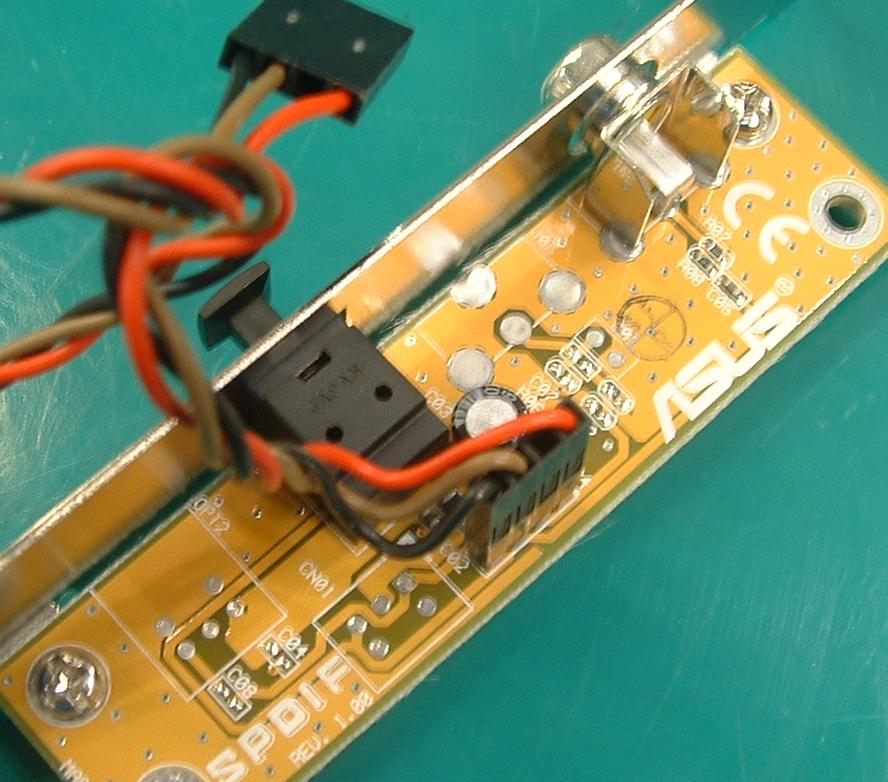
Here's a photograph of it (attached, blurry) from the ASUS estore site. In this, one can see that the S/PDIF output (top right) is merely an RCA jack connecting *almost* directly to the feed from the motherboard.

But before it gets to the jack, it passes through a capacitor, and then a voltage divider (two resistors in series between the the S/PDIF-OUT signal and GND, with the RCA jack tapping from the middle point between the two resistors.

My questions are: what values should I use for the capactor and the resistors, in making my own connector board? Let's assume the motherboard S/PDIF-OUT signal uses TTL logic levels (I can verify this.. just haven't done it yet).

???


Attachments
291395-spdif3.jpg (1932 downloads)


Edited by mlord (01/12/2006 15:26)

Top
#291025 - 01/12/2006 15:35 Re: TTL to S/PDIF voltage divider? [Re: mlord]
mlord
carpal tunnel

Registered: 29/08/2000
Posts: 14484
Loc: Canada
Further to this, S/PDIF over RCA/coax is supposed to use 0.5V - 1.0V signal levels, so the voltage divider should be easy enough to size up -- just not sure of the current draw requirements for S/PDIF, and thus the magnitude of restance to use. Say, 3kOhm and 1kOhm for a divide-by-4 ? Or a similar ratio with smaller resistors?

And I imagine that pretty much any capacitor in the pico-farad range would probably be fine for that component (?).

Top
#291026 - 01/12/2006 15:36 Re: TTL to S/PDIF voltage divider? [Re: mlord]
tman
carpal tunnel

Registered: 24/12/2001
Posts: 5528
Try a 100nF cap, 330 ohm resistor and a 100 ohm resistor. I'm assuming the board already has a buffer in it somewhere. I made a few of these for various things a while ago and they were the values I used.

Code:

TTL ----||-----[ 330ohm ]------+---- S/PDIF
|
100 Ohm
|
Gnd ---------------------------+----


Top
#291027 - 01/12/2006 16:50 Re: TTL to S/PDIF voltage divider? [Re: tman]
mlord
carpal tunnel

Registered: 29/08/2000
Posts: 14484
Loc: Canada
Quote:
Try a 100nF cap, 330 ohm resistor and a 100 ohm resistor. I'm assuming the board already has a buffer in it somewhere. I made a few of these for various things a while ago and they were the values I used.

Super. Exactly what I was hoping for, thanks!

Cheers

Top
#291028 - 01/12/2006 17:15 Re: TTL to S/PDIF voltage divider? [Re: mlord]
maczrool
pooh-bah

Registered: 13/01/2002
Posts: 1649
Loc: Louisiana, USA
Indeed, our digital out board uses similar values. 374 and 90.9 ohm resistors and also a 100nf cap.

You might also wish to add an isolation transformer to prevent hum from leaking in if you have ground loops.

Stu
_________________________
If you want it to break, buy Sony!

Top
#291029 - 03/12/2006 09:33 Re: TTL to S/PDIF voltage divider? [Re: mlord]
Shonky
pooh-bah

Registered: 12/01/2002
Posts: 2009
Loc: Brisbane, Australia
If you can wait a few days (I'm in the process of moving), I have one of these that came with an ASUS motherboard. I can read/measure the values for you...
_________________________
Christian
#40104192 120Gb (no longer in my E36 M3, won't fit the E46 M3)

Top
#291030 - 03/12/2006 13:20 Re: TTL to S/PDIF voltage divider? [Re: Shonky]
mlord
carpal tunnel

Registered: 29/08/2000
Posts: 14484
Loc: Canada
Quote:
If you can wait a few days (I'm in the process of moving), I have one of these that came with an ASUS motherboard. I can read/measure the values for you...


Thanks. I've already got the ASUS dongle on order, and in the meanwhile I stuck my logic analyser onto the pins and ... nothing. Either it's borken, or the s/w is borken. I'll try again later, after other problems get addressed.

Cheers

Top