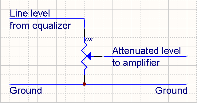
You need to think of the potentiometer as a variable voltage divider not a resistor. When wired as a voltage divider the resistance value of the potentiometer is much less critical. The line level signal from the equalizer will always be connected across the full resistance of the potentiometer. With the potentiometer fully counter clockwise the input to the amplifier is effectively grounded giving you infinite attenuation. With the potentiometer fully clockwise the equalizer is effectively connected directly to the amplifier giving you no attenuation. As you turn the potentiometer the resistance values in the voltage divider formed by the potentiometer vary.

When selecting a value for the potentiometer the main factor is the input impedance of the amplifier. The input impedance of the amplifier will be connected in parallel with the resistance in the bottom leg of the voltage divider. To maintain a linear attenuation over the full range the resistance value of the potentiometer needs to be significantly lower than the input impedance of the amp. I had a look in the manual for your amps and they have an input impedance of 10K which is lower than I expected. A 1K potentiometer should do nicely.
A 1/4W potentiometer is more that adequate for this application. Yes line level signals really are that puny.
Rod.

 Previous Topic
 Index
Index
