#226751 - 23/07/2004 16:52
 Re: 5th Meet
[Re: tfabris]
Re: 5th Meet
[Re: tfabris]
|
carpal tunnel

Registered: 25/12/2000
Posts: 16706
Loc: Raleigh, NC US
|
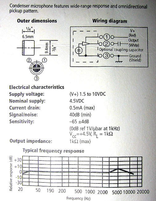
The mechanical drawing lists the red wire as the "power supply wire" and the gray wire(s?) as the "output wire". That doesn't really help me, but maybe it'll mean something to someone else.
_________________________
Bitt Faulk
|
|
Top
|
|
|
|
|
#226752 - 24/07/2004 19:25
Re: 5th Meet
[Re: wfaulk]
|
carpal tunnel

Registered: 20/12/1999
Posts: 31636
Loc: Seattle, WA
|
Here is a clearer schematic, from the back of the box. From the looks of it, this microphone needs to be powered. Not sure.
Anyone?
|
|
Top
|
|
|
|
|
#226753 - 24/07/2004 19:32
Re: 5th Meet
[Re: tfabris]
|
old hand

Registered: 14/02/2002
Posts: 804
Loc: Salt Lake City, UT
|
Under the white wire it says "Optional coupling capacitor". Think that means the white is optional? The others it says exactly what they are, Output and Ground. I should really take and electronics class sometime....
_________________________
-Michael
#040103696 on a shelf
Mk2a - 90 GB - Red - Illuminated buttons
|
|
Top
|
|
|
|
|
#226754 - 24/07/2004 19:35
Re: 5th Meet
[Re: Waterman981]
|
carpal tunnel
Registered: 20/12/1999
Posts: 31636
Loc: Seattle, WA
|
You're reading it wrong.
Red= V+
White = Output
Shield = Gnd
The "optional coupling capacitor" refers to the capacitor symbol drawn on the white (output) wire.
|
|
Top
|
|
|
|
|
#226755 - 24/07/2004 19:50
Re: 5th Meet
[Re: tfabris]
|
carpal tunnel

Registered: 17/01/2002
Posts: 3996
Loc: Manchester UK
|
That sucker needs volts.
The diagram shows a little triangle, that's an amp hence it needs power. I'm sure you could power it off a battery. However it's probably easier to just get one that doesn't need power.
_________________________
Cheers,
Andy M
|
|
Top
|
|
|
|
|
#226756 - 24/07/2004 20:01
Re: 5th Meet
[Re: andym]
|
carpal tunnel
Registered: 20/12/1999
Posts: 31636
Loc: Seattle, WA
|
Actually, I happened to have a little two-double-A battery holder sitting here with a couple of wires hanging off of it. I'm trying that next.
|
|
Top
|
|
|
|
#226757 - 24/07/2004 20:02
 Re: 5th Meet
[Re: tfabris]
Re: 5th Meet
[Re: tfabris]
|
old hand
Registered: 14/02/2002
Posts: 804
Loc: Salt Lake City, UT
|
Doh!  I see now what you mean... Have to look closer next time!
_________________________
-Michael
#040103696 on a shelf
Mk2a - 90 GB - Red - Illuminated buttons
|
|
Top
|
|
|
|
|
#226758 - 24/07/2004 20:26
Re: 5th Meet
[Re: andym]
|
carpal tunnel
Registered: 20/12/1999
Posts: 31636
Loc: Seattle, WA
|
Quote:
However it's probably easier to just get one that doesn't need power.
Anyone have any idea which radio shack part number would be the correct one, then?
Adding 3v power to this one works, however its output level is quite low.
|
|
Top
|
|
|
|
|
#226759 - 24/07/2004 20:42
Re: 5th Meet
[Re: tfabris]
|
carpal tunnel

Registered: 17/12/2000
Posts: 2665
Loc: Manteca, California
|
It would be low on only 3v. Try patching in a 3rd battery to bring it up to 4.5v.
_________________________
Glenn
|
|
Top
|
|
|
|
|
#226760 - 24/07/2004 21:14
Re: 5th Meet
[Re: gbeer]
|
carpal tunnel
Registered: 20/12/1999
Posts: 31636
Loc: Seattle, WA
|
Quote:
It would be low on only 3v. Try patching in a 3rd battery to bring it up to 4.5v.
I just tried 9 volts on it (was easier than patching in a 3rd AA batery), and got the exact same output level. Recorded myself into Sound Recorder saying the same thing at the same volume level with the same distance from the mic, once with 3v power and once with 9v power. Same level of output when the two wav files were played back. They were both very quiet (needed to turn my speakers up all the way to hear it) but very clean.
|
|
Top
|
|
|
|
|
#226761 - 25/07/2004 01:43
Re: 5th Meet
[Re: tfabris]
|
Quiet One

Registered: 28/01/2004
Posts: 0
Loc: Athens, Greece
|
First of all, a liitle 101 on microphones: there are 2 kinds: Dynamic - They are somewhat the opposite of speakers (sound waves move a coil in a magnet), are extremely directional (they have a "cardioid" response in horizontal level) and are typically used in drum sets and some high end models as cheap alternatives in various applications where good performance is required (community radio would be a good example). They don't need to be supplied with power and they don't come in small sizes. Condenser - They are in essence a capacitor, as the diaphragm is placed over a back plate and as the diaphragm vibrates to sound waves the capacitance between the two changes. For them to work the diaphragm must be polarized, hence the need for power. Condenser mics are omni-directional (when you see a mic on a round table or the mics worn on clothes in TV you can safely bet it's a condenser one although there are exceptions), have generally better frequency response than dynamic ones but are susceptible to room volume and ambient noises. Now to the point: The schematic you have is obviously wrong since the way it is drawn it clearly indicates a short between power and ground (1 and 3). I think the black dot was intended to go after the triangle. That also explains the "optional coupling capacitor" that is there to cut off DC and let just the signal go through (and I think that may be why you are having poor performance with yours). This is all more thoroughly explained here from where I'm copying the following: Code:
       vcc
        O
        |
        /
        \
        /
        \  EQUAL TO REQUIRED IMPEDANCE
        /  EX.= 1000 Ohm
        \
        |
        |     CAPACITOR MOST ANY VALUE 10uF 16v
|---|   |  + | /
|   |---0----| |-------   AUDIO OUT
|   |        | \
|   |----O--------------
|---|    |
         |
       -----
        ---
         -
Now what made me wonder is John Graley's post where he claims "Both Radio Shack microphones are condensor types and will be compatible with the car player's input (I think the phantom power supply is about 3V in a car player)." Now I did measure with my multimeter and tada, there IS an aprox. 4.5V power supply on the mic connector, so I guess you can just plug wires 2 on the tip and 3 on the ring of the empeg connector and it should work ( i.e. the coupling capacitor should be inside the empeg somewhere and the mic will "feed" by power provided from the unit). Or perhaps you might need to connect 1 and 2 together on the tip if the mic refuses to work out of the white wire. Sorry for the length and hope this helps. Dimitris Zarafonitis.
|
|
Top
|
|
|
|
|
#226762 - 25/07/2004 04:25
Re: 5th Meet
[Re: dizar]
|
pooh-bah
Registered: 12/01/2002
Posts: 2009
Loc: Brisbane, Australia
|
Quote:
The schematic you have is obviously wrong since the way it is drawn it clearly indicates a short between power and ground (1 and 3). I think the black dot was intended to go after the triangle. That also explains the "optional coupling capacitor" that is there to cut off DC and let just the signal go through (and I think that may be why you are having poor performance with yours).
Actually that schematic is correct. It does not show a short to ground at all. The triangle is a preamp (op-amp) inside the mic somewhere. That's pretty standard having the power connections come in either side of the op-amp diagram.
Thus the 3 connections to the mic.
_________________________
Christian
#40104192 120Gb (no longer in my E36 M3, won't fit the E46 M3)
|
|
Top
|
|
|
|
#226763 - 25/07/2004 10:57
 Re: 5th Meet
[Re: Shonky]
Re: 5th Meet
[Re: Shonky]
|
Quiet One
Registered: 28/01/2004
Posts: 0
Loc: Athens, Greece
|
Quote:
The triangle is a preamp (op-amp) inside the mic somewhere.
So that's what it (clearly  ) is ) is
Andy M mentioned it too, but I didn't notice. As I glanced at the schematic it seemed like line 1 was going under the op-amp not like a component with 4 connections. My bad.
So I guess this means for Tony that 1+2 go into the tip of the connector and 3 on the ring. This should work since emped does have phantom power so it must have the coupling capacitor in it's circuit internaly or else it would feed DC to it's mic stage.
The (oversimplified) schematic should look like this:
Code:
                         empeg unit

                        ------------------------

                        |                      |

                        |                      |

                        |  |  vcc              |

                        |  /                   |

                        |  \                   |

                        |  /                   |

           ---------    |  \                   |

           |       |    |  |                   |

|---|   --------   |    |  |   | /             |

|   |---|OP-AMP|---o-------0---| |--           |

|   |   --------        |      | \   AUDIO     |

|   |      |            |             OUT      |

|   |------O--------------------o----          |

|---|                   |       |              |

                        |      ---             |

                        |       -              |

                        ------------------------
Cheers.
Edit: Allthough now that cofee has kicked in I can't help but think that a capacitor is needed between the op-amp output and the point where red and white wires get joined to cut off DC coming onto the op-amp's output. Hence the reference to the optional coupling capacitor on the mic's schematics.
Which should be lesson enough to not post a) before bed and b) after just having waked up 
Code:
                         empeg unit

                         ------------------------

                         |                      |

                         |                      |

                         |  |  vcc              |

                         |  /                   |

                         |  \                   |

                         |  /                   |

           ------------  |  \                   |

           |          |  |  |                   |

|---|   --------  \ | |  |  |   | /             |

|   |---|OP-AMP|--| |-o-----0---| |--           |

|   |   --------  / |    |      | \   AUDIO     |

|   |      |             |             OUT      |

|   |------O---------------------o----          |

|---|                    |       |              |

                         |      ---             |

                         |       -              |

                         ------------------------
Edited by dizar (25/07/2004 11:47)
|
|
Top
|
|
|
|
|
#226764 - 25/07/2004 14:16
Re: 5th Meet
[Re: dizar]
|
carpal tunnel
Registered: 20/12/1999
Posts: 31636
Loc: Seattle, WA
|
This is very good information. Now the only real remaining question is whether I need the capactior or not.
Question: The capacitor, doesn't it change the frequency response of the microphone?
|
|
Top
|
|
|
|
|
#226765 - 25/07/2004 14:29
Re: 5th Meet
[Re: tfabris]
|
carpal tunnel
Registered: 20/12/1999
Posts: 31636
Loc: Seattle, WA
|
Hm, I've got a box of 0.1uF capactiors, would that work?
... And I'm not clear on which direction (plus or minus) the leads are supposed to go in the schematic. For that matter, I'm not sure which leads are plus or minus on these capactiors. They're little ceramic jobbies, ratshack part number 272-109a. It's not like an LED where one lead is longer than the other, they're both the same length...
|
|
Top
|
|
|
|
|
#226766 - 25/07/2004 14:43
Re: 5th Meet
[Re: tfabris]
|
pooh-bah

Registered: 02/06/2000
Posts: 1996
Loc: Gothenburg, Sweden
|
Quote:
little ceramic jobbies
Most likely non-polarized...
_________________________
/Michael
|
|
Top
|
|
|
|
|
#226767 - 25/07/2004 15:04
Re: 5th Meet
[Re: mtempsch]
|
carpal tunnel
Registered: 20/12/1999
Posts: 31636
Loc: Seattle, WA
|
Thanks. Okay, tried it with the 0.1uF capacitor in place trying to use phantom power on the signal line as drawn. Works, but is quieter than when I supply the voltage myself without the capacitor. Since I'm plugging into my SoundBlaster Live instead of the empeg, it's possible that the soundcard doesn't supply phantom power at all.
Still don't know whether this capacitor is changing the frequency response or not?
|
|
Top
|
|
|
|
|
#226768 - 25/07/2004 16:22
Re: 5th Meet
[Re: tfabris]
|
Quiet One
Registered: 28/01/2004
Posts: 0
Loc: Athens, Greece
|
Quote:
Thanks. Okay, tried it with the 0.1uF capacitor in place trying to use phantom power on the signal line as drawn. Works, but is quieter than when I supply the voltage myself without the capacitor. Since I'm plugging into my SoundBlaster Live instead of the empeg, it's possible that the soundcard doesn't supply phantom power at all.
Still don't know whether this capacitor is changing the frequency response or not?
Check here again about 1/4 down the page where it says "Soundcards and electret microphones". Check the whole section as it has many alternative wiring methods for soundcards. Apparently SB has a stereo plug that uses "Input Wiring: Audio on Tip, Ground on Sleeve, 5Volts DC Bias on Ring" as mentioned on the page.
In other words, if you use SB then you can connect ground/red/white to sleeve/ring/tip respectively and it will work without a capacitor (if you have a stereo jack, then it would be interesting to let us know the results this way). If you used a mono jack on the SB, then you're not feeding the mic any power. On the empeg just use a capacitor and a 2 conductor wire (coaxial preferable).
I don't think the capacitor will (significantly) alter the frequency responce of the microphone.
Cheers.
|
|
Top
|
|
|
|
|
#226769 - 25/07/2004 16:26
Re: 5th Meet
[Re: dizar]
|
carpal tunnel
Registered: 20/12/1999
Posts: 31636
Loc: Seattle, WA
|
Thanks, makes sense. Quote:
I don't think the capacitor will (significantly) alter the frequency responce of the microphone.
Since the purpose of auto-EQ is precise frequency adjustment, even small changes in the frequency response would be undesirable. Anyone know just how much the capacitor would change the frequency response if at all?
|
|
Top
|
|
|
|
|
#226770 - 25/07/2004 17:28
Re: 5th Meet
[Re: tfabris]
|
carpal tunnel
Registered: 17/01/2002
Posts: 3996
Loc: Manchester UK
|
How will the empeg provide this power? Bearing in mind the jack is mono.
_________________________
Cheers,
Andy M
|
|
Top
|
|
|
|
|
#226771 - 25/07/2004 17:42
Re: 5th Meet
[Re: andym]
|
carpal tunnel
Registered: 20/12/1999
Posts: 31636
Loc: Seattle, WA
|
Quote:
How will the empeg provide this power? Bearing in mind the jack is mono.
On the signal line (tip of plug) as phantom power, just as drawn in the schematics above. Signal line does double duty: supplies power as well as sensing the signal.
|
|
Top
|
|
|
|
|
#226772 - 25/07/2004 18:04
Re: 5th Meet
[Re: tfabris]
|
carpal tunnel
Registered: 17/01/2002
Posts: 3996
Loc: Manchester UK
|
Never heard of single ended phantom power. Then again I try not slum it in domestic audio.
_________________________
Cheers,
Andy M
|
|
Top
|
|
|
|
|
#226773 - 25/07/2004 21:37
Re: 5th Meet
[Re: tfabris]
|
Quiet One
Registered: 28/01/2004
Posts: 0
Loc: Athens, Greece
|
Tony, Try the following 2 on your SB: Code:
           ----------------------- TIP
           |
|---|   --------  \ |
|   |---|OP-AMP|--| |------------- RING
|   |   --------  / |
|   |      |
|   |------O---------------------- SLEEVE
|---|


                             | /
           ------------   ---| |-- TIP
           |          |   |  | \
|---|   --------  \ | |   |
|   |---|OP-AMP|--| |-o---o------- RING
|   |   --------  / |
|   |      |
|   |------O---------------------- SLEEVE
|---|
Schematic 1 is the ideal, while 2 is closer to what you'll get on the empeg. Try recording with the two configurations and see what goes on. I would suggest recording the same parts of a track out of your stereo with the mic in the exact same position and the volume untouched. If you get significant difference try using capacitors nearer the 10uF value (or even bigger) of high-quality plastic film type. Also bear in mind the voltage of your capacitors (the 16V offered in the aforementioned page is OK for a theoretical maximux 10V voltage). If I understand the theory in this correctly, the capacitors will not in any way alter the response FREQUENCY WISE since the signal is of alternating nature and measured in the range of a few hundred mVolts max. There is a chance though that you will get weak signal, that's why I'm suggesting experimenting a little with the capacitance and you can also try adding a resistor as in the following shematic to adjust to the input impedance that is 600 to 1500 Ohms in SB. I have a tie clip type condenser here that uses a 22uF after its 1.35 volts button battery and a 1000 Ohms resistor. Code:
                             | /
           ---/\/\/\---   ---| |-- TIP
           |          |   |  | \
|---|   --------  \ | |   |
|   |---|OP-AMP|--| |-o---o------- RING
|   |   --------  / |
|   |      |
|   |------O---------------------- SLEEVE
|---|
Me has no idea what the input impedance is on the empeg, but I'm quessing roughly the same as the SB. Cheers. PS. OTOH, istead of going through all this trouble, you could just go and get yourself a 2 wire condenser 
|
|
Top
|
|
|
|
|
#226774 - 25/07/2004 23:32
Re: 5th Meet
[Re: dizar]
|
carpal tunnel
Registered: 20/12/1999
Posts: 31636
Loc: Seattle, WA
|
Quote:
istead of going through all this trouble, you could just go and get yourself a 2 wire condenser
See, that's the problem. I want to get the exact correct mic that can be used for the auto-EQ feature on the v3a8 player software. I came to this thread and was directed to that radio shack part number. So was that part number wrong?
If so, then what is the right part number?
|
|
Top
|
|
|
|
|
#226775 - 26/07/2004 05:54
Re: 5th Meet
[Re: tfabris]
|
addict
Registered: 27/10/2002
Posts: 568
|
I'm not sure if they'd work, but you can put them either way. They're not polarized. Just try and see if it works.
It's a long time since I last read about these microphones, but I seem to remember that you'd need to put a resistor between pin 1 and 2. A Google should turn up something about them...
Stig
Edit: Looks like I just replied to an earlier post.... Think I need to check my cache settings. Bummer...
Edit 2: I think a 0.1uF cap is too small. I know that an amplifier I built used a 2.2uF at the input. And yes, the cap will affect the frequency-curve. It will be a LF-filter, but I can't remember much of the theory. It's about 16 years since I learnt (and used) it...
Edited by StigOE (26/07/2004 06:41)
|
|
Top
|
|
|
|
|
#226776 - 26/07/2004 15:19
Re: 5th Meet
[Re: StigOE]
|
journeyman
Registered: 30/01/2002
Posts: 56
Loc: Cambridge, UK
|
Oooh dear it lookes like I've got a lot of catching up to do. The AutoEQ is not optimised for any particular mic. It assumes the microphone has a flat frequency response. The better the mic you use, the better the AutoEQ will perform, but for thorectially perfect results, you would have to know the frequency response of your mic and correct for it afterwards (by simply adjusting the eq gains manually). Now, my idea about nominating a particular model of microphone for a "standard" is simply that we can determine its frequency response and share that info between everyone who has the same mic. Rather like internet standards, consistency is more important than quality. However, it turns out that radio shack were rude enough not to mention in their datasheet that the KUC1515-01-0850 is a 3 lead model. This makes it hard to connect to the player without additional components, and those component values will affect frequency repsonse... thereby undermining our attempts sharing a measured frequency response. The question is, how many people have bought one? If lots of you guys have then we now need to invent a recommended standard way of connecting the KUC1515-01-0850 to the car player otherwise I will un-recommend the KUC1515-01-850 and pick something else with 2 leads to recommend instead. I couldn't find a circuit on http://www.hut.fi/Misc/Electronics/circuits/microphone_powering.html for connecting a mic such as KUC1515-01-850 to a car player. I would have thought, referring to Tony's image that - empeg ground to mic ground
- empeg signal to mic power (red) via 3.3K resistor
- empeg signal also to mic signal (white) via 4.7uF capacitor
might work from looking at the car player schematics (basically trying to seperate AC signal from DC power). Cheers, John
|
|
Top
|
|
|
|
|
#226777 - 26/07/2004 15:33
Re: 5th Meet
[Re: JonnyGee]
|
pooh-bah

Registered: 12/02/2002
Posts: 2298
Loc: Berkeley, California
|
At a total of $4, I'm pretty sure most people would be willing to buy a seccond more appropriet one should they have already bought the radio shack one.
Matthew
|
|
Top
|
|
|
|
|
#226779 - 26/07/2004 21:11
Re: 5th Meet
[Re: JonnyGee]
|
old hand
Registered: 14/02/2002
Posts: 804
Loc: Salt Lake City, UT
|
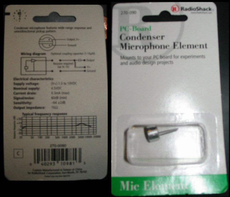
I stopped in Radio Shack today and found a 2 conductor Omnidirectional Condenser microphone for $1 less than the other one. Model number 270-090 (no docs on radioshack.com) The frequency response looks the same. From its wiring diagram it looks to do just like what we were saying before combining the power and output leads. It puts both power and output on the same lead, but wants a resistor later when it is split up(this would be inside the empeg?)
Differences from Tony's include:
Supply Voltage: 1.0 to 10VDC
Current Drain: 0.3mA (max)
Signal/noise: 60dB(min)
Sensitivity: -64 + or - 2dB
And now for the crappy pics! Sorry, no camera with macro capability.

Next to wiring diagram it says "Optional coupling capacitor (1-10 ufd)" and between the wires it says: "Resistor required (up to 1k)"
_________________________
-Michael
#040103696 on a shelf
Mk2a - 90 GB - Red - Illuminated buttons
|
|
Top
|
|
|
|
|
#226780 - 27/07/2004 08:44
Re: 5th Meet
[Re: Waterman981]
|
journeyman
Registered: 30/01/2002
Posts: 56
Loc: Cambridge, UK
|
Looks hopeful. How about this time we try out the mic first and then standardise on it once we're sure it's suitable.
If others have the 3-wire mic and are impatiant to try out the feature, I suggest in the meantime using either batteries or my suggested circuit to run the mic and have a go... it will take a while to get used to the EQ. Remember to turn off shuffle, xfade etc and set EQ locks to independant.
Cheers, John
|
|
Top
|
|
|
|
|
|

 Previous Topic
 Index
Index