#231625 - 26/08/2004 03:49
 Potentiometer for amplifier remote gain control
|
carpal tunnel

Registered: 08/07/1999
Posts: 5561
Loc: Ajijic, Mexico
|
I have a pretty complex stereo setup in my car. (see attached picture)
My signal path goes from head unit through a line driver to a 30-band stereo equalizer, and from there it is split 5 ways and each of the five signals goes into its own small potentiometer built into the armrest between the front seats so that each signal can be individually adjusted from the driver's seat before going to one of the five class-T amplifiers. (I have one amplifier for each speaker pair: Dash, center channel, doors, rear roof, and subwoofers)
I am not happy with the potentiometers.
They do not have a wide enough range of attenuation, and they are not very linear in operation.
To clarify: the attenuation seems to range from zero attenuation (signal goes straight through) to a maximum of perhaps 20 dB. And if I set the potentiiometer to maximum attenuation, and then turn it so that the sound becomes louder, the first two-thirds of the rotation seems to have no effect at all on the sound, then in the last third of the knob turning the sound gets loud very quickly.
I want potentiometers that will give me attenuation ranging from none to at least 40 decibels. Ideally, I'd like to be able to turn the signal to the amp completely off. And I'd like some semblence of linearity, where (for example) if the potentiometer would produce 45 decibels of attenuation through its 270 degrees of rotation of the knob, I could figure on getting about 5 decibels change for each 30 degrees of knob twisting.
Just to make things harder... these potentiometers have to be pretty compact, no more than two inches / 5 CM in diameter, oh, and they have to be double pole, i.e., stereo.
To make things easier, they are handling very little current -- just the pre-amp signal from my empeg after passing through the line driver -- probably about six or eight volts, low current.
Can anybody recommmend suitable potentiometers for this application, and suggest where I might buy them?
tanstaafl.
Attachments
230745-SHOST80%.jpg (130 downloads)
_________________________
"There Ain't No Such Thing As A Free Lunch"
|
|
Top
|
|
|
|
#231626 - 26/08/2004 08:34
 Re: Potentiometer for amplifier remote gain control
[Re: tanstaafl.]
Re: Potentiometer for amplifier remote gain control
[Re: tanstaafl.]
|
journeyman
Registered: 04/05/2000
Posts: 84
Loc: Australia
|
I'm not sure if you want to wire this from scratch yourself. If you do it is easy to do with a standard dual gang 50k logarithmic potentiometer. Available from Farnell, Radio Shack, etc. The potentiometer needs to be logarithmic to give you the perception of a linear increase in volume.
You would connect the output of the equalizer to the top of the potentiometer and ground to the bottom of the potentiometer. The wiper of the potentiometer will then connect to the amplifier. This will then allow you to adjust the volume to the amp from straight through to infinite attenuation. If you didn't want to attenuate down to zero you could put some resistance in the ground leg of the pot.
If you're keen to wire this yourself I'll draw up a circuit, it's a bit hard to put into works but a very simple circuit.
Rod.
|
|
Top
|
|
|
|
|
#231627 - 26/08/2004 08:58
Re: Potentiometer for amplifier remote gain control
[Re: Rod]
|
carpal tunnel
Registered: 15/08/2000
Posts: 4859
Loc: New Jersey, USA
|
...the SHO Wagon...  Not only does it sound fantastic, but it will outperform many racecars...
_________________________
Paul Grzelak
200GB with 48MB RAM, Illuminated Buttons and Digital Outputs
|
|
Top
|
|
|
|
|
#231628 - 26/08/2004 19:56
Re: Potentiometer for amplifier remote gain control
[Re: tanstaafl.]
|
carpal tunnel

Registered: 25/06/1999
Posts: 2993
Loc: Wareham, Dorset, UK
|
You are using linear law pots instead of Log law, which is the correct one for audio gain applications (your ear works logarithmically also).
I would recommend Nylar foil pots, not cheap, but no crackle and they last a long time. A company called Sychron used to make them in the UK years ago, but I can't find any reference to them now.
_________________________
One of the few remaining Mk1 owners...  #00015 #00015
|
|
Top
|
|
|
|
|
#231629 - 04/09/2004 02:15
Re: Potentiometer for amplifier remote gain control
[Re: Rod]
|
carpal tunnel
Registered: 08/07/1999
Posts: 5561
Loc: Ajijic, Mexico
|
standard dual gang 50k logarithmic potentiometerCan you tell me if this is what I am looking for? Question: Why 50K? I have no idea of what an appropriate resistance would be, and am willing to take your word for it that 50K is right... but what does that 50K get me? My goal would be virtually complete silence on one end, and zero attenuation on the other. Is that what 50K will do in this instance? If it is of any significance, the signal is going through a line driver before it gets to the equalizer, and the potentiometers will be receiving it at about 6 volts. As you can see, they are available in everything from 1,000 ohms to 1 billion ohms maximum resistance. 50K is the optimum? Question: Is the 1/4 watt power dissipation figure shown in the data sheet a sane number? Again, I have no idea of how much power these pots might have to dissipate if turned to maximum resistance. Does that depend on the size and nature of the amplifiers? They are all 100 watts/channel Class T amplifiers, feeding speakers that are wired 4-Ohm. tanstaafl.
_________________________
"There Ain't No Such Thing As A Free Lunch"
|
|
Top
|
|
|
|
|
#231630 - 04/09/2004 02:31
Re: Potentiometer for amplifier remote gain control
[Re: tanstaafl.]
|
Carpal Tunnel

Registered: 08/02/2002
Posts: 3411
|
Yeah, the audio taper series.
The way that Rod suggested to set this up (that any sane electronic engineer would concur with) is using the pot as a voltage divider. (google...)
In this application the actual resistance is non-critical, The major requirement is that the resistance is large enough to avoid current issues (power dissipation etc), 50K meets that fine.
_________________________
Mk2a 60GB Blue. Serial 030102962
sig.mp3: File Format not Valid.
|
|
Top
|
|
|
|
|
#231631 - 05/09/2004 03:52
Re: Potentiometer for amplifier remote gain control
[Re: genixia]
|
carpal tunnel
Registered: 08/07/1999
Posts: 5561
Loc: Ajijic, Mexico
|
In this application the actual resistance is non-critical, The major requirement is that the resistance is large enough to avoid current issues (power dissipation etc), 50K meets that fine.
OK, now I am confused. (As if that were difficult to accomplish!)
As I understand it, the resistance is going to vary from 0 ohms to 50,000 ohms, depending on how far around I crank the knob on the potentiometer.
At no attenuation (zero resistance) the power from the signal line just passes straight through, no heat dissipation problems, no reduction in sound from the amplifier.
What happens at maximum attenuation (50,000 ohms)? Isn't that where the maximum power has to be dissipated? Will the potentiometer then have to dissipate more than the listed 1/4 watt? Will the signal reaching the amplifier be effectively reduced to nothing?
If I visualize this correctly, other values of potentiometers (like 10K, or 30K, or 100K etc.) differ only in the maximum amount of reduction of signal strength to the amplifier. For the sake of the argument, lets hypothesize that a 30K resistance would achieve my desired "effectively nothing" signal to the amp. In that case, the remaining 40% of the 50K potentiometer would be wasted, overkill, and my useful range of adjustment on the potentiometer would only be the first 180 degrees (out of the total 300 degrees) of rotation. Or, to take the argument to extremes, if I used the 1000K potentiometer, after the first nine degrees of rotation (starting at the zero attenuation point) the amplifier would be receiving no signal, making accurate adjustment difficult.
This is why I keep coming back to that 50K figure. Yes, 50K will (probably?) bring the signal strength down to zero. But if 25K would do the same thing, then I would get twice the "resolution" when it came to making the fine adjustments.
So, what is the optimal resistance, assuming I want at least a 40dB reduction in output while minimizing granularity on the tuning? Is this calculable, or should I just order a whole bunch of pots of different values and do it by trial and error?
Finally, that 1/4 watt maximum power dissipation still bothers me. 1/4 watt really isn't very much. A bulb in a penlight uses more power than that. Is a line-level audio signal really so puny? I don't work with this stuff, so I really have no feel for it at all...
tanstaafl.
_________________________
"There Ain't No Such Thing As A Free Lunch"
|
|
Top
|
|
|
|
|
#231632 - 05/09/2004 05:36
Re: Potentiometer for amplifier remote gain control
[Re: tanstaafl.]
|
pooh-bah

Registered: 02/06/2000
Posts: 1996
Loc: Gothenburg, Sweden
|
Depends on how you set it up. With your suggested series connection of the peotentiometer, the value is somewhat more critical and 50k might not be suitable. The required resitance would depend on the input impedance (resistance) of the amplifier/headunit aux in/whatever. If the potentiometer was of the same size as the input impedance, you can at max drop 50% of the voltage across the potentiometer - which means a 3dB attenuation. If you want more, then the potentiometer needs to be larger than the input impedance... But the use suggested above isn't the "usual way". Instead hook up the signal source to the "ends" of the potentiometer and wire the amplifier to one end and the slider. If you don't want it capable of turning it down to 0, you can attach a fixed resistance at one end - your max attenuation is now R/(P+R) times (recalc to dB not done...) Something like this: Code:
*-------
        |
        P
        P
        P<---------*
        P
        |           To input on amp
        R
        R
        |
*--------------------*
As to the power requirements... Say you've got a signal source that provides a 4V RMS signal. Power developed (P=U^2/R) into 50k is 4^2/50k = 16/50.000 = 0.00032W For a true and proper power calculation one would have to consider the effects of the parallell connection with the amp input and whether parts of the potentiometer could handle things in whatever position the slider is in. But with 50k, the margins should be sufficient so that more detailed calculations can be avoided.
_________________________
/Michael
|
|
Top
|
|
|
|
|
#231633 - 05/09/2004 11:38
Re: Potentiometer for amplifier remote gain control
[Re: tanstaafl.]
|
carpal tunnel

Registered: 20/12/1999
Posts: 31636
Loc: Seattle, WA
|
Quote:
What happens at maximum attenuation (50,000 ohms)? Isn't that where the maximum power has to be dissipated? Will the potentiometer then have to dissipate more than the listed 1/4 watt?
Aren't you talking about line-level here, before the amplifier? I don't think the amount of energy dissipated is a factor in this case. You're thinking of back in the days when you put those special speaker attenuator pots on the actual speaker wires.
|
|
Top
|
|
|
|
|
#231634 - 06/09/2004 01:51
Re: Potentiometer for amplifier remote gain control
[Re: tanstaafl.]
|
journeyman
Registered: 04/05/2000
Posts: 84
Loc: Australia
|
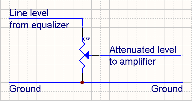
You need to think of the potentiometer as a variable voltage divider not a resistor. When wired as a voltage divider the resistance value of the potentiometer is much less critical. The line level signal from the equalizer will always be connected across the full resistance of the potentiometer. With the potentiometer fully counter clockwise the input to the amplifier is effectively grounded giving you infinite attenuation. With the potentiometer fully clockwise the equalizer is effectively connected directly to the amplifier giving you no attenuation. As you turn the potentiometer the resistance values in the voltage divider formed by the potentiometer vary.

When selecting a value for the potentiometer the main factor is the input impedance of the amplifier. The input impedance of the amplifier will be connected in parallel with the resistance in the bottom leg of the voltage divider. To maintain a linear attenuation over the full range the resistance value of the potentiometer needs to be significantly lower than the input impedance of the amp. I had a look in the manual for your amps and they have an input impedance of 10K which is lower than I expected. A 1K potentiometer should do nicely.
A 1/4W potentiometer is more that adequate for this application. Yes line level signals really are that puny.
Rod.
|
|
Top
|
|
|
|
|
#231635 - 06/09/2004 02:01
Re: Potentiometer for amplifier remote gain control
[Re: tanstaafl.]
|
journeyman
Registered: 04/05/2000
Posts: 84
Loc: Australia
|
Quote:
the signal is going through a line driver before it gets to the equalizer
Shouldn't the line driver be after the equalizer so that the output of the equalizer doesn't have to drive all the amps?
Rod.
|
|
Top
|
|
|
|
|
#231636 - 06/09/2004 13:43
Re: Potentiometer for amplifier remote gain control
[Re: Rod]
|
Carpal Tunnel
Registered: 08/02/2002
Posts: 3411
|
Quote:
I had a look in the manual for your amps and they have an input impedance of 10K which is lower than I expected.
That sounds rather unusual. Definitely not FET inputs!
_________________________
Mk2a 60GB Blue. Serial 030102962
sig.mp3: File Format not Valid.
|
|
Top
|
|
|
|
|
|

 Previous Topic
 Index
Index