#61417 - 20/01/2002 13:31
 UTP Cabling Problems
|
carpal tunnel

Registered: 18/01/2000
Posts: 5694
Loc: London, UK
|
As I posted here a couple of weeks ago, I was looking for some solution to network the ground and first floors of my house. I've given up on the wireless solution -- too expensive right now -- so I went with running cable down the outside of the house.
Diagram:
Switch <- cat5 -> Wall |- cat5 -| Wall <- cat5 -> hub (uplink) <- cat5 -> empeg
I cabled both ends according to the diagram inside the wall plate[1].
This is almost working correctly. I get link lights on the switch upstairs and the hub downstairs. I don't, however, seem to be getting any packets to make their way downstairs -- I'm seeing DHCPREQUEST packets on the server upstairs, but the DHCPOFFER packets don't seem to be making it back downstairs.
The other oddity is that I get a lot of collisions if I plug the cable into the uplink port on the downstairs hub, which I wasn't expecting. If I plug it into a normal port, I get no collisions. I get link in both cases, it seems.
The rest of the patch cables are fine -- I tested them separately [2], and the hub and switch have talked to eachother in the past.
So, questions:
1. Which pairs are actually used on the cable, and for what? I'm considering swapping one of the unused pairs over, in case there's a break in the cable somewhere.
2. If I want the uplink port to work, which pairs do I need to swap on the back of the wallplate?
Advice?
[1] except that the wall plate diagram showed blue-and-white and white-and-blue (etc.) on the terminals, which confused the issue slightly.
[2] And besides, I'm a UTP crimping god -- I've not done a single bad crimp yet (touch wood-effect desktop).
_________________________
-- roger
|
|
Top
|
|
|
|
#61418 - 20/01/2002 13:53
 Re: UTP Cabling Problems
[Re: Roger]
Re: UTP Cabling Problems
[Re: Roger]
|
carpal tunnel

Registered: 20/12/1999
Posts: 31636
Loc: Seattle, WA
|
Are they wired in the proper pairs?
It's not supposed to be straight pair-pair-pair-pair on pins 1-8. A certain set of wires is supposed to "jump" between the pairs to help prevent inductive noise on the cable.
Someone here on the BBS posted a cat-5 wiring diagram recently, anyone have that handy?
|
|
Top
|
|
|
|
|
#61419 - 20/01/2002 13:59
Re: UTP Cabling Problems
[Re: tfabris]
|
carpal tunnel
Registered: 18/01/2000
Posts: 5694
Loc: London, UK
|
It's not that -- at least where the cable's concerned -- I lifted that picture a while ago, and put a copy here.
It could be the case for the wall plates -- the punch block had the wires in pairs: green/g+w, orange/o+w, etc.
I wasn't sure how the wall plates should be cabled, so I just followed the pictures. This has resulted in the external cable run appearing to be a cross-over, which means I don't have to use the uplink port. This is confusing, and I should perhaps fix this. But more importantly, I get link on both ends, but packets only go one way.
_________________________
-- roger
|
|
Top
|
|
|
|
|
#61420 - 20/01/2002 14:15
Re: UTP Cabling Problems
[Re: Roger]
|
carpal tunnel
Registered: 18/01/2000
Posts: 5694
Loc: London, UK
|
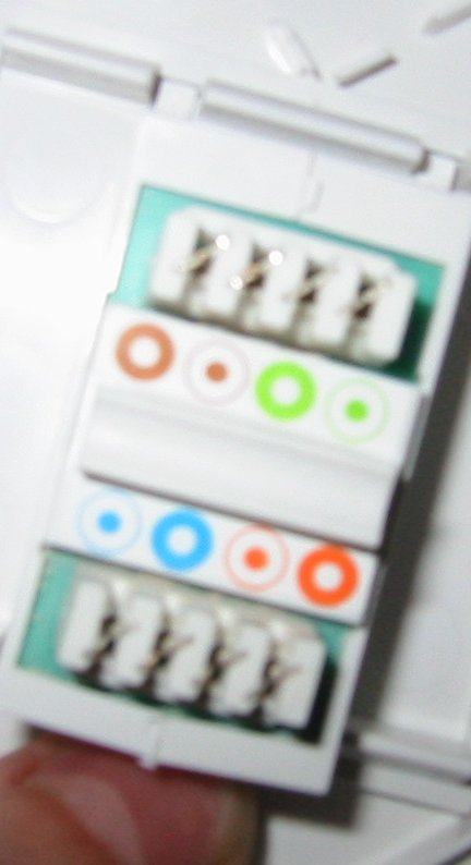
Photos of one of the wall plates are here. I took one with the flash, and one with a light shining on it instead. I've boosted the colour saturation, to make the colouring clearer.
The other is wired exactly the same way -- I hope.
_________________________
-- roger
|
|
Top
|
|
|
|
|
#61421 - 20/01/2002 14:38
Re: UTP Cabling Problems
[Re: Roger]
|
carpal tunnel
Registered: 20/12/1999
Posts: 31636
Loc: Seattle, WA
|
Can't tell from the photos which punch-down terminals go to which pins on the jack. Maybe you should check that with a continuity tester to make sure the pins are going where you want them to go. Maybe it's that simple, just re-punching to match the jack layout?
|
|
Top
|
|
|
|
|
#61422 - 20/01/2002 15:37
Re: UTP Cabling Problems
[Re: Roger]
|
carpal tunnel

Registered: 25/06/1999
Posts: 2993
Loc: Wareham, Dorset, UK
|
The terminal posts on these wall connectors are known as KRONE, insulation displacement type. I can see from the photos that you don't have the insertion tool (used to be 70 quid + in the early 80s, Lord alone knows how much now). The reason I say that is that I can see you are using the way we used to do it when we didn't have the tool, i.e. bridge a large piece of the wire across the contact cutters and then force down the wire on each side with each hand. You then trim off the excess. It works pretty well, but not always, and relies on the perpendicularity of the wire across the blades.
There are a few conditions:
- Krone connectors simply do not work well with multi-core wire; they are designed to take single core telephony wires. UTP is not always single core, which you would need to check.
- if you do use multi-core, there is no guarantee that the insulation will be cut properly on insertion, since the wire bundle tends to collapse under the compression of the blades, hence it looks as if it has cut OK, but hasn't.
- you cannot use overgauge insulated wire, or the blades seperate under insertion and do not cut the insulation, as above.
- you cannot use the double insulated wire that looks like it has the right gauge as it only cuts the outside sheath, and not always the inner. Again, as above.
- some UTP cable actually uses a nylon thread core, with copper ribbon woven in for conductivity. This type of cable is used for IDC type connectors, but the sort that cuts into the thread perpendicular to it, along it's axis (RJ type connectors). The thread collapses if you use lateral blade IDC devices, across it's axis.
From your symptoms, you describe one dead IDC joint in 16 connections; not inconceiveable.
You should be able to make a loopback test adaptor by taking an RJ connector with a short length of cable. Loop back 1-2, 3-4, 5-6, 7-8. Plug it in the wall socket and go to the other end. With a multi-meter, ping out 1-2, 2-3 etc. and if all 4 loops are good, then you have made 16 good joints, 8 at each socket. If any one of the pairs fails, then you should re-make all 4 joints for that pair at both ends of the cable.
Not trying to be critical, since I suspect (as you say) that you are good at this. However, this advice comes from 4 years of frustration with this IDC system working in Telecoms, where this problem happened over, and over, and over again wasting many hours trouble shooting. For wall fittings, I would always go for screw or clamp connection types, never Krone (unless I had the Krone cut-and-insert tool).
The Farnell part number for the insertion tool is 147-894.
And no, I no longer know where the one I stole^H^H^H^H^Hborrowed back in 1986 is, sorry! 
Are there any small telephony companies that do office exchange installations anywhere near Signet Court? Maybe you could borrow the tool as I am certain they would have one. They wouldn't be able to exist without one!
_________________________
One of the few remaining Mk1 owners...  #00015 #00015
|
|
Top
|
|
|
|
|
#61423 - 20/01/2002 15:54
Re: UTP Cabling Problems
[Re: Roger]
|
pooh-bah

Registered: 13/01/2002
Posts: 1649
Loc: Louisiana, USA
|
If you are using fast ethernet, all the pairs are used (half for transmitting and half for receiving). Pointing an RJ-45 plug at you and looking from above with the contacts on top, pin one starts on the right and pin 8 is on the left. If you are using standard 10 mb/s ethernet, then the blue (pin 4), blue/white (pin 5), brown/ white (pin 7), and brown (pin 8) are unused. Green/white (pin 3) and green (pin 6) are used for receiving; orange/white (pin 1) and orange (pin 2) are used for transmitting.
If you are using an uplink port, then you don't want to swap any of the wires, this is done internally by the device with the uplink port. It assumes you are using a straight-through wiring scheme.
Make sure your wiring between the wall plate and the RJ-45 connector on the other end where the hub or switch is has contiuity in the same places (on the same colors/colours) as a verified working patch cable has. If not rewire the wall plates to match. Also make sure your wire run is no more than 330 feet and doesn't run parallel to any electrical wires.
_________________________
If you want it to break, buy Sony!
|
|
Top
|
|
|
|
|
#61424 - 20/01/2002 16:54
Re: UTP Cabling Problems
[Re: maczrool]
|
carpal tunnel

Registered: 12/11/2001
Posts: 7738
Loc: Toronto, CANADA
|
Fast ethernet (100baseTX) uses the same two pairs as 10baseT. It most definitely doesn't use all 4 pairs. If it did, then it would be pretty miraculous how I've been running 100baseTX all these years without connecting two pairs.  You can check documentation all over the place, including CISCO to verify this.
My first guess regarding Roger's problem would be bad connections, not broken wires. I have always used solid core wire and have used both a punch-down tool as well screw-down wall terminals (which is what I'm using right now).
When putting in a new wall plate at a friend's house we ran into a similar problem. The replacement plate was not like the original. It was meant to have all the pairs wired IN ORDER. ie. you didn't skip pin 4 and 5 when wiring the TX lines. This was a bang-your-head-on-the-wall scenario once we found out.
Continuity testers are nice, but if you don't have access to one, you can also isolate the problem by using different runs of known-good patch cord, skipping various connecting segments as you isolate.
Bottom line: I would check the wiring requirements of the wall plates.
And for good measure: standard is: 1 & 2 are RX (+ and -) and 3 & 6 are TX (+ and -)
Bruno
|
|
Top
|
|
|
|
|
#61425 - 20/01/2002 17:05
Re: UTP Cabling Problems
[Re: hybrid8]
|
carpal tunnel

Registered: 08/06/1999
Posts: 7868
|
1000BaseT and TX do need the 4 pairs though (they shoot 250mbps down each pair at the same frequency as 100BaseTX).
Anyone know if there are cheap gigabit hubs yet? I've seen some NICs at reasonable prices, but not the hubs.
|
|
Top
|
|
|
|
|
#61426 - 20/01/2002 17:06
Re: UTP Cabling Problems
[Re: tfabris]
|
carpal tunnel
Registered: 18/01/2000
Posts: 5694
Loc: London, UK
|
Surely I don't care which cores go to which pins, as long as both ends are wired the same? The colours are only for convenience, no?
_________________________
-- roger
|
|
Top
|
|
|
|
|
#61427 - 20/01/2002 17:15
Re: UTP Cabling Problems
[Re: schofiel]
|
carpal tunnel
Registered: 18/01/2000
Posts: 5694
Loc: London, UK
|
Actually, I used a hacked-up plastic telecoms insertion tool. It seemed to (not quite) work. What I was hoping is that, from the symptoms, someone could tell me which colour I have to repunch. I could go and pick up a cheaper knock-off Krone part, which I might have more success with -- there's a Maplin in town.
It's single-insulated solid-core cable (with an outer sheath insulating all of the pairs) -- "Acolan CTD100 4 pair 24 AWG UTP Category 5 PVC Grey, product number M0880A" -- it says on the box.
I don't quite understand the instructions for the loop-back test. Could you elaborate?
_________________________
-- roger
|
|
Top
|
|
|
|
|
#61428 - 20/01/2002 17:19
Re: UTP Cabling Problems
[Re: maczrool]
|
carpal tunnel
Registered: 18/01/2000
Posts: 5694
Loc: London, UK
|
So, I might need to repunch green and green/white downstairs or orange and orange/white upstairs?
This is on the assumption that the packets are being transmitted from downstairs and received upstairs correctly, but either not being transmitted correctly upstairs or being received correctly downstairs.
What I might do is fake it up with the face plates and a short segment of cat5 to ensure that I've got the crossover-ness sorted first.
_________________________
-- roger
|
|
Top
|
|
|
|
|
#61429 - 20/01/2002 17:22
Re: UTP Cabling Problems
[Re: hybrid8]
|
carpal tunnel
Registered: 18/01/2000
Posts: 5694
Loc: London, UK
|
you can also isolate the problem by using different runs of known-good patch cord
Care to elaborate? As you might have guessed, I've been down the pub with Hugo, so I'm not visualising this as clearly as I might do.
Otherwise, thanks to everyone for the plethora of advice. I'll investigate some of these avenues tomorrow, when I'm sober enough to work a wire stripper without endangering life and limb .
Of course, each failed attempt means that I have less and less wire at each end to play with, and I'm getting closer and closer to the wall. Pretty soon, I'll need to run a fresh stretch .
_________________________
-- roger
|
|
Top
|
|
|
|
|
#61430 - 20/01/2002 17:37
Re: UTP Cabling Problems
[Re: drakino]
|
carpal tunnel
Registered: 12/11/2001
Posts: 7738
Loc: Toronto, CANADA
|
And even with 100baseTX you don't want the non-used pairs connected incorrectly - this will possibly add noise. I've never mismatched their connections to verify, but even Cisco mentions this.
Bruno
|
|
Top
|
|
|
|
|
#61431 - 20/01/2002 17:46
Re: UTP Cabling Problems
[Re: Roger]
|
carpal tunnel
Registered: 12/11/2001
Posts: 7738
Loc: Toronto, CANADA
|
If you have bought a box of cable you should still have plenty of cable that currently isn't stuffed through your walls, right? So you can use some of that for testing. Otherwise, if you already had a long patch cord that you know works (test it with a tester or with your PC to a hub) then you could use that.
The idea is to use that cord to make connections around the various wall plates and other connections you now have. This will allow you to start ruling out the different connection points for problems. If you bypass everything you've installed, then you know if the devices are good, etc.. It's just a way to be able to exclude your new connections to find where the problem is.
Works well in car audio as well - run a good RCA pair outside the car when trying to isolate problems with your connections inside.
So, you still come online to post when pissed? Staying away from strippers is probably a good idea. Though that didn't stop me from going to Centerfolds in San Francisco a week and a half ago. And that was after a night of bowling and clubbing. Oh wait, I don't think we're talking about the same kind of strippers. 
Bruno
|
|
Top
|
|
|
|
|
#61432 - 20/01/2002 18:43
Re: UTP Cabling Problems
[Re: Roger]
|
carpal tunnel
Registered: 20/12/1999
Posts: 31636
Loc: Seattle, WA
|
Surely I don't care which cores go to which pins, as long as both ends are wired the same? The colours are only for convenience, no?
Wrong. This is a very common mistake.
The pairs have to be twisted properly, or crosstalk and noise between the wires will kill you on long cable runs and produce strange errors. The color coding is so that you know which wires are twisted with which other wires.
That's why the color coding is important.
This is one reason why I don't recommend newbies crimp their own cat-5 cables...
|
|
Top
|
|
|
|
|
#61433 - 20/01/2002 19:36
Re: UTP Cabling Problems
[Re: hybrid8]
|
pooh-bah
Registered: 13/01/2002
Posts: 1649
Loc: Louisiana, USA
|
Okay, you are right about fast ethernet having only 2 pairs in use. I read otherwise somewhere a while ago. Sorry for the misinformation!
About the continuity tester. I just used a 9 volt battery, and an LED to verify proper continuity. The battery was connected with clip leads and some small guage wire to two of the contacts on a patch cord plugged into a wall plate. Then an LED was touched againsted the corresponding RJ-45 contacts on the other end of the cable (the cable attached to the back side of the wall plate) where it was to plug into the switch. If it lit up, then I knew it was wired properly, or at least would work. I just repeated this until all of the wires were checked. This is how I found what I was doing wrong in my wiring of seven rooms in the house. Now even the longest run of about 200 feet (60 meters) works as well (same throughput) as a 1 meter crossover patch cord.
_________________________
If you want it to break, buy Sony!
|
|
Top
|
|
|
|
|
#61434 - 21/01/2002 03:51
Re: UTP Cabling Problems
[Re: tfabris]
|
carpal tunnel
Registered: 13/07/2000
Posts: 4184
Loc: Cambridge, England
|
The color coding is so that you know which wires are twisted with which other wires.
Indeed. It doesn't matter which pair you use for which signal, but you must pair the pairs properly. Green is twisted with green-and-white, etc.
BTW Krone/Katt/110 multi-standard insertion tools are fifteen quid from Netshop.
Peter
|
|
Top
|
|
|
|
|
#61435 - 21/01/2002 04:15
Re: UTP Cabling Problems
[Re: peter]
|
carpal tunnel
Registered: 18/01/2000
Posts: 5694
Loc: London, UK
|
you must pair the pairs properly
...so I wouldn't have gone far wrong by following the pretty picture on the back of the plate -- which you can't see in the photos, 'cos I removed it to get the punch tool close enough.
Simply sounds like a problem with the punchblock -- I've borrowed a multimeter, so I'll check the pin assignments and continuity this evening.
fifteen quid from Netshop
...whose website was down over the weekend, or I would have bought the stuff from there.
_________________________
-- roger
|
|
Top
|
|
|
|
|
#61436 - 21/01/2002 06:03
Re: UTP Cabling Problems
[Re: maczrool]
|
carpal tunnel

Registered: 25/12/2000
Posts: 16706
Loc: Raleigh, NC US
|
100BaseT4 was one implementation of 100Mbps (Fast) Ethernet, and it did use all four pairs. It requires that the NICs and the hubs support it, and I've never seen ones that support both it and 100BaseTX. Never seen it in use, though, anyway.
_________________________
Bitt Faulk
|
|
Top
|
|
|
|
|
#61437 - 21/01/2002 14:24
Re: UTP Cabling Problems
[Re: Roger]
|
carpal tunnel
Registered: 18/01/2000
Posts: 5694
Loc: London, UK
|
Right, I've just spent some time on ICQ with Tony, and he had some good advice. Unfortunately, it looks like the wallplates are bogus.
I just plugged a (known-good) piece of CAT5 into the front, and then used a multimeter to check the connections (one probe on loose end of CAT5, other on the blades on the back of the plate).
My findings are these:
1. Orange and white doesn't appear to be connected at all.
2. Green, Blue and Blue/White appear to be common.
These findings apply to both plates. Either it's a bad batch, or these aren't actually meant for Ethernet. Do these pin assignments make any sense for any other cabling standard anyone knows? (I'm guessing Rob Schofield will be able to think of some arcane mil-spec standard from the 70's )
I'm going to crack one of them open and see if there's a solder bridge or anything in there...
_________________________
-- roger
|
|
Top
|
|
|
|
|
#61438 - 21/01/2002 14:29
Re: UTP Cabling Problems
[Re: Roger]
|
carpal tunnel
Registered: 18/01/2000
Posts: 5694
Loc: London, UK
|
OK, reading back through this thread, it seems that blue and blue/white are unused, so I shouldn't have to worry about them being common with green, which is used (except for possible induction problems?)
I _should_ be worrying about the orange/white -- 'cos it's used for TX.
Sound fair?
_________________________
-- roger
|
|
Top
|
|
|
|
|
#61439 - 21/01/2002 14:37
Re: UTP Cabling Problems
[Re: Roger]
|
carpal tunnel
Registered: 25/06/1999
Posts: 2993
Loc: Wareham, Dorset, UK
|
Hang on - you say these are 8-way RJ11s. Do your UTP connectors just go straight into the socket OK?
These might be ISDN wallplates with a pre-wiring PCB - they do use Krone connectors after all: these are pretty horrible excresences designed to make it "easy" to DIY ISDN installs. They are, however, sod all use for anything else since the pre-wire PCB grounds together certain leads so allow a good reference for the incoming exchange signal (in spite of them supposedly being differential).
You said there was a label on the back, can you scan or re-draw it and post it?
_________________________
One of the few remaining Mk1 owners... #00015
|
|
Top
|
|
|
|
|
#61440 - 21/01/2002 14:50
Re: UTP Cabling Problems
[Re: schofiel]
|
carpal tunnel
Registered: 18/01/2000
Posts: 5694
Loc: London, UK
|
OK, picture of the back of the plate attached. The side of the block says "Enhanced NET: Enhanced Category 5 T568B/258A"
Obviously, this is some new definition for "enhanced" I wasn't aware of .
_________________________
-- roger
|
|
Top
|
|
|
|
|
#61441 - 21/01/2002 14:51
Re: UTP Cabling Problems
[Re: Roger]
|
carpal tunnel
Registered: 18/01/2000
Posts: 5694
Loc: London, UK
|
So, anyway, you can see what I mean about the confusing colour scheme. Checking with a multimeter reveals that (at least for brown), the outer colour means brown, whereas the inner colour means brown-and-white, IYSWIM.
_________________________
-- roger
|
|
Top
|
|
|
|
|
#61442 - 21/01/2002 14:53
Re: UTP Cabling Problems
[Re: schofiel]
|
carpal tunnel
Registered: 18/01/2000
Posts: 5694
Loc: London, UK
|
Do your UTP connectors just go straight into the socket OK?
Yes, except for a little tightness in the way that the retracting flap doesn't retract quite far enough.
_________________________
-- roger
|
|
Top
|
|
|
|
|
#61443 - 21/01/2002 16:27
Re: UTP Cabling Problems
[Re: Roger]
|
addict
Registered: 05/05/2000
Posts: 623
Loc: Cambridge
|
There's an insertion tool in the office somewhere (not the fancy expensive one, but it managed to do all the sockets in the office).
I've come across dodgy wallplates before - in the past I've traced it to the metal wire contacts on the socket making poor contact.
|
|
Top
|
|
|
|
|
#61444 - 22/01/2002 13:23
Re: UTP Cabling Problems
[Re: Roger]
|
carpal tunnel
Registered: 25/06/1999
Posts: 2993
Loc: Wareham, Dorset, UK
|
Hhmmmm... I now confess to being stumped. I have had a look at the plate and it actually looks as if the colour scheme is right for CAT-5 UTP pairs. However, if you say that there are commoned connections in the connector, where each one is presented at the back as a seperate terminal, then it's maybe any of:
- shorts inside the connector itself - spring contacts bent together in the aperture? Solder blobs inside? Loose multi-strand inside the connector?
The only time I have seen shorted together terminals has been on these useless "Easy Wire" sockets, but the pattern is different to what you have buzzed out. It eliminates one useful pair, which doesn't make any sense.
OK, I know you stuck a cable in the front (known good) and buzzed between cable end and backplate, but have you done this ONLY on the backplate, ie. 1-2, 1-3, 1-4 etc. 2-1, 2-3, etc. and built a truth table? This way you eliminate the cable completely. I'm going to keep thinking about this, but I am stumped at the moment.
_________________________
One of the few remaining Mk1 owners... #00015
|
|
Top
|
|
|
|
|
#61445 - 22/01/2002 15:37
Re: UTP Cabling Problems
[Re: schofiel]
|
carpal tunnel
Registered: 18/01/2000
Posts: 5694
Loc: London, UK
|
have you done this ONLY on the backplate
I have now. It gets strange at this point. The backplate is as you'd expect -- the only 1's in my truth table are down the diagonal -- i.e. 1 goes to 1, 2 goes to 2, but nothing else.
Now, as soon as I connect the cable to the other side of the block, I get the same behaviour as described before: blue, blue/white and green become common.
Right, further investigation reveals that I'll have to hand back my "king-of-crimps" crown -- my "known-good" cable ain't so good. Somehow the (you've guessed it) blue, blue/white and green cores are common .
Beginning again with another piece of cable -- this time one that I've checked properly -- not just for continuity but for inter-core isolation, we find:
That the truth table is now correct.
And, in fact, after faffing around a bit (i.e. crimping it a bit harder) with my (now checked properly cable), that I've now got connectivity with pin 1.
Hmmm.
I'm going to check one other piece of cable, and if that's good, I'll put it all back together and let you know how I got on.
It's a little embarrassing, and I'm sorry to have led you all on a wild goose chase, but at least I've learnt something....
_________________________
-- roger
|
|
Top
|
|
|
|
|
#61446 - 22/01/2002 15:59
Re: UTP Cabling Problems
[Re: Roger]
|
carpal tunnel
Registered: 18/01/2000
Posts: 5694
Loc: London, UK
|
Hmmm, the plot thickens...
both of my "known-good" cables (one now known to be not-so-good) fail to work properly with the wallplates, or even with my hub. This is very odd.
Anyway, it now seems to be the cables, so I'm going to put the wallplates back on, and see if that works.
_________________________
-- roger
|
|
Top
|
|
|
|
|
|

 Previous Topic
 Index
Index