#316815 - 01/12/2008 15:08
 Re: not powering up
[Re: crazyplums]
Re: not powering up
[Re: crazyplums]
|
carpal tunnel

Registered: 29/08/2000
Posts: 14548
Loc: Canada
|
Based on your observations thus far, there's an open circuit (broken connection) somewhere between the +12V input and the empeg ground plane. The path for this is supposed to go through that fuse.
Once you have the board out the case, measure it again. It should be near zero ohms.
Also measure the resistance from the outside contact of the DC power jack and the fuse (either side). This should also be near zero ohms.
And one more: the black wire on the 4-wire cable nearby is also supposed to follow the same path -- it should measure zero ohms between it and the fuse, and between it and the outside contact of the DC power jack.
Cheers
|
|
Top
|
|
|
|
|
#316816 - 01/12/2008 15:26
Re: not powering up
[Re: mlord]
|
carpal tunnel
Registered: 29/08/2000
Posts: 14548
Loc: Canada
|
Here is another photo of the area under scrutiny. I have labelled some of the key test points, to ease discussion of exactly where to probe etc..
1. The outside (negative) contact of the DC power jack.
2. The 2.5A GND fuse contact (the top surface is the other contact).
3. The NEG(-) contact for the black wire (unplugged) from the docking connector.
4. A small coil that connects the fuse to the empeg ground plane -- the contact is deep inside the hole here.
5. The other contact of the small coil (I don't know which contact is which).
What you should do, is measure ohms between all combinations of those red dots, plus across the two contacts of the fuse itself, and post your complete findings here.
The ground circuit actually goes from points 1 and 3, through the fuse at point 2, and then through the coil (points 4,5), after which it finally connects to ground/chassis of the rest of the empeg.
There is a nearly identical lead-in circuit for the POS(+) side of the power, with a second fuse and a second half of the coil for that. But that stuff appears to be working in your player, so ignore it.
Cheers
Attachments
 Description: The +12V PSU front end of a Mk2a RioCar. Description: The +12V PSU front end of a Mk2a RioCar.
Edited by mlord (01/12/2008 15:34)
|
|
Top
|
|
|
|
|
#316826 - 01/12/2008 17:39
Re: not powering up
[Re: mlord]
|
member

Registered: 29/12/2006
Posts: 159
Loc: E.Sussex, UK
|
ah, i can see a difference already.
the fuse i was testing is between the 4 pin input plug and the coil. between 3&4 on your (very helpful) diagram.
where you have a fuse (fig2), i have a black component. markings on it are
22-35
LD 2
the empeg in question is a empeg car, ser No080000166 if that makes a difference.
sorry if i wasn't clear in the initial post, when i saw your pic with the screw and the fuse, i only saw the one in mine and didn't think to re-check your pic.
Hugh
will test the, other bits now, they all look the same.
|
|
Top
|
|
|
|
|
#316831 - 01/12/2008 18:06
Re: not powering up
[Re: crazyplums]
|
member
Registered: 29/12/2006
Posts: 159
Loc: E.Sussex, UK
|
right....
found another of the black fuses, or at least what i think is a fuse? used this as a guide to test the one i have in place of the silver fuse in your pic. both read 3.3 m/ohms across them
1 to 2 (unreadable, keeps increasing or decreasing in .5 increments, one reading it's m/ohms, the next k/ohms.
1-3 88k/ohms
1-4 10.01 k/ohms
1-5 10.01 k/ohms
3-4 81 k/ohms
3-5 80.7 k/ohms
4-5 1.9 ohm
1-chassis 9 k/ohms
did i miss any? any reading connecting to fig 2 (fuse) was not a steady reading, wild variations.
it looks like this pcb might have been out before, one of the pcb screws is a bit messy, think i'll take the pcb out just to see if the black fuse is a repair.
Edited by crazyplums (01/12/2008 18:22)
|
|
Top
|
|
|
|
|
#316838 - 01/12/2008 20:21
Re: not powering up
[Re: crazyplums]
|
carpal tunnel
Registered: 29/08/2000
Posts: 14548
Loc: Canada
|
Oh.. you have a Mk2, not a Mk2a.
Ignore all of that, then.
I'll post new instructions / photo shortly.
-ml
|
|
Top
|
|
|
|
|
#316852 - 02/12/2008 07:21
Re: not powering up
[Re: mlord]
|
member
Registered: 29/12/2006
Posts: 159
Loc: E.Sussex, UK
|
thanks for the continued support, Mark. very much appreciated  I didn't think to check which model it was, assumed it was the same as my 2a, doh! ok, i'll test the pcb in a minute, the only difference between the pic you've posted, and my player, is that on my board, which is now completely out the chassis -fwiw- there is a component in the space between the 3v jumper and the dc jack, the component is the same as in the top right of your pic, 22-35 LN, i thought it was a replacememnt fuse at first, but is it a diode? i'm sure they used to have a mark one end to show which direction the let the current flow.... it's been nearly 20yrs since i messed at this level! in fact, i'd say there's very little on these pcb's i recongnise, all seems to be chips, no little pot capacitors, triacs, colour coded resistors, etc!! does that make me old school! ok, results... 1-2 10.02 k/ohm 1-3 97.8 k/ohm 1-4 10.01 k/ohm 1-5 10.01 k/ohm 2-3 86.5 k/ohm (slowly climbing) 2-4 3.1 ohm 2-5 3.1 ohm 3-4 85.7 k/ohm 3-5 86 k/ohm 4-5 3.1 ohm thanks. Hugh
|
|
Top
|
|
|
|
|
#316853 - 02/12/2008 09:44
Re: not powering up
[Re: crazyplums]
|
addict
Registered: 27/10/2002
Posts: 568
|
The component is a capacitor, 22uF/35V, and the line is positive side.
Without having a Mk2 at hand (I only have a couple of Mk2a, and they're not at hand either), it looks like the fuse is blown. Did you check the fuse? Those m/ohms you reported earlier, that was Megaohms, not milliohms, right?
Stig
|
|
Top
|
|
|
|
|
#316854 - 02/12/2008 09:48
Re: not powering up
[Re: StigOE]
|
member
Registered: 29/12/2006
Posts: 159
Loc: E.Sussex, UK
|
The component is a capacitor, 22uF/35V, and the line is positive side.
Without having a Mk2 at hand (I only have a couple of Mk2a, and they're not at hand either), it looks like the fuse is blown. Did you check the fuse? Those m/ohms you reported earlier, that was Megaohms, not milliohms, right?
Stig to be ashamedly honest.... i wasn't sure if it was megaohms or milli ohms, so i just put m/ohms, like multi meter said!! any idea why i have a capacitor where the picture above shows a blank space? between the dc jack and the 3v jumper i mean. cheers. Hugh
|
|
Top
|
|
|
|
|
#316855 - 02/12/2008 10:04
Re: not powering up
[Re: crazyplums]
|
addict
Registered: 27/10/2002
Posts: 568
|
to be ashamedly honest.... i wasn't sure if it was megaohms or milli ohms, so i just put m/ohms, like multi meter said!!
any idea why i have a capacitor where the picture above shows a blank space? between the dc jack and the 3v jumper i mean.
cheers.
Hugh No worries, just wanted to make sure. If it's just a plain ordinary multimeter, it should be megaohms. No idea about the capacitor. Just read a bit further up the thread again and saw you had tested the fuse already. Broken trace somewhere between fuse and coil, maybe? Stig
|
|
Top
|
|
|
|
|
#316857 - 02/12/2008 11:44
Re: not powering up
[Re: StigOE]
|
member
Registered: 29/12/2006
Posts: 159
Loc: E.Sussex, UK
|
i think it might be the dc jack.
going by the image above, the neg is the pin on the right of the jack with the number 1 on it,
the neg side of the dc input is obviously going to connect with the flat spring connection on the inside of the female jack, and the pos to the pin in the female jack.
using a simple continuity test, there is no connection between the flat inside the female, and the No1 connection shown above. the pos tests out fine.
however... there is a neg continuity to a pin directly underneath the jack socket. due to the pcb being quite thick and multi layered i cannot see where this leads too, even holding it to a 300w light!
I have to admit, this pcb is some piece of work, when i was building boards (QC / test, hand finishing chips etc) back in 90/92, it was all big resistors, caps, etc. i knew all the resistor values by the colours, what the numbers meant on other components, etc, i don't even know what half of what i'm loking at in the empeg is!
surface mount stuff was barely seen, and when i say surface mount, i mean like on the empeg board, most components a fraction of the size i dealt with, and soldered on top of the board, not behind it. I've fixed many a device by tracing earthing / power faults on the pcb themselves, broken / burnt track, etc, and repairing them, but i wouldn't want to attempt this baby! heck, even my fine tips on my irons are twice the size of the smallest solder joints on the empeg!
still, i was 15/17yr old when i used to do all that, latterly more used to fixing circuits etc that you could poke your finger into if you'd not got a probe! not even done them for 4 years!
|
|
Top
|
|
|
|
|
#316858 - 02/12/2008 11:49
Re: not powering up
[Re: StigOE]
|
carpal tunnel
Registered: 29/08/2000
Posts: 14548
Loc: Canada
|
Just read a bit further up the thread again and saw you had tested the fuse already. Broken trace somewhere between fuse and coil, maybe?
Stig The Mk2 has only a single power fuse, on the +12V input. His player appears to have a break between the GND input and the empeg mainboard ground. So the fuse doesn't enter into it. And from the measurements given, it pretty much has to be in (or very near to) the DC power jack itself. Time to dig out a magnifying glass, and look VERY VERY closely at the pads around number 1. Maybe look at the backside of the board too. Is the DC jack *really* connected to an unbroken/unlifted pad on the mainboard ? Cheers
Edited by mlord (02/12/2008 11:49)
|
|
Top
|
|
|
|
|
#316859 - 02/12/2008 11:55
Re: not powering up
[Re: crazyplums]
|
carpal tunnel
Registered: 29/08/2000
Posts: 14548
Loc: Canada
|
i think it might be the dc jack. Oh, bugger! I got the jack pins confused. Number "1" in my photo is meaningless.. you need to test against the third post, which goes through the board and is accessible from the underside. EDIT: very important: plug the AC-adapter into the jack before measuring -- but DO NOT PLUG IT INTO THE AC MAINS! Just a quick ohms from there to numbers 3, 4, 5 will do nicely. Cheers
Edited by mlord (02/12/2008 11:55)
|
|
Top
|
|
|
|
|
#316860 - 02/12/2008 11:56
Re: not powering up
[Re: mlord]
|
carpal tunnel
Registered: 29/08/2000
Posts: 14548
Loc: Canada
|
i think it might be the dc jack. Oh, bugger! I got the jack pins confused. Number "1" in my photo is meaningless.. you need to test against the third post, which goes through the board and is accessible from the underside. EDIT: very important: plug the AC-adapter into the jack before measuring -- but DO NOT PLUG IT INTO THE AC MAINS! Just a quick ohms from there to numbers 3, 4, 5 will do nicely. Actually, I believe the third post is also accessible at the bottom solder pad in my photo -- where the NEG side of that extra capacitor you have it is soldered on. EDIT: actually, that capacitor is not extra -- it's simply missing for some reason from my own Mk2 unit here.
Edited by mlord (02/12/2008 12:01)
|
|
Top
|
|
|
|
|
#316862 - 02/12/2008 11:59
Re: not powering up
[Re: mlord]
|
carpal tunnel
Registered: 29/08/2000
Posts: 14548
Loc: Canada
|
..and after you confirm that the jack is indeed broken, email me your postal address and I'll mail you a factory replacement jack. That's assuming you can desolder the old one without frying the board (both things are easy to do..) and then solder on the new one.
Cheers
|
|
Top
|
|
|
|
|
#316864 - 02/12/2008 13:48
Re: not powering up
[Re: mlord]
|
member
Registered: 29/12/2006
Posts: 159
Loc: E.Sussex, UK
|
thanks Mark,
new readings, male jack inserted,
ground pin (1) under jack / pcb.
to ...
earth / screw 2......... 16.4 k/ohm
pin on male plug 3....... 3.2 ohm
coil 4........... 16.4 k/ohm
coil 5......... 16.4 k/ohm
from side pin
1-2, 9.9 k/ohm
1-3, 26.3 k/ohm
1-4, 9.9 k/ohm
1-5, 9.9 k/ohm
male jack not inserted...
from underside pin,
1-2, 8.7 k/ohm
1-3, 3.1ohm
1-4, 8.85 k/ohm
1-5, 8.85 k/ohm
from side pin
1-2 8.82 k/ohm
1-3, fluctuates 13-14 ohm
1-4, 8.8 k/ohm
1-5, 8.8 k/ohm
thanks again,
replacing the plug shouldn't be a problem,
Hugh
|
|
Top
|
|
|
|
|
#316865 - 02/12/2008 14:25
Re: not powering up
[Re: mlord]
|
carpal tunnel

Registered: 08/07/1999
Posts: 5561
Loc: Ajijic, Mexico
|
EDIT: actually, that capacitor is not extra -- it's simply missing for some reason from my own Mk2 unit here. Would that be this capacitor? From the empeg FAQ: Now, with all of that said, some early models of Mk2 (not 2a) players were fitted with EMC capacitors that tended to reduce the extreme high frequencies of the front car outputs and the home outputs (but not the rear car outputs). These capacitors were meant to reduce noise, but it was later discovered that they were not needed, and they were removed from subsequent board revisions.tanstaafl.
_________________________
"There Ain't No Such Thing As A Free Lunch"
|
|
Top
|
|
|
|
|
#316866 - 02/12/2008 14:30
Re: not powering up
[Re: tanstaafl.]
|
member
Registered: 29/12/2006
Posts: 159
Loc: E.Sussex, UK
|
HI Tanstaafi,
in short, no!
look at the photo on marks post, page 4, the 2nd photo looking forward from the rear.
top right of the pic there are three black rectangular cap's in question, now, bottom left of the pic, between the jjack socket, and the 3v jumper, are two soldered pads, empty, the cap sits there, paralell to the jack socket.
Hugh
|
|
Top
|
|
|
|
|
#316868 - 02/12/2008 15:08
Re: not powering up
[Re: tanstaafl.]
|
carpal tunnel

Registered: 20/12/1999
Posts: 31636
Loc: Seattle, WA
|
Would that be this capacitor? Nope, they're working on the other end of the board, in the power section over by the AC adapter input. The cap in that FAQ entry is connected to the audio circuit over by the car dock connector.
|
|
Top
|
|
|
|
|
#316869 - 02/12/2008 15:54
Re: not powering up
[Re: tfabris]
|
old hand
Registered: 20/07/1999
Posts: 1102
Loc: UK
|
If the DC jack is faulty in such a way that the switch contact doesn't operate (tied to ground) the unit will not power up at all. The power control pic software requires the switch input to be pulled up to +5v before it will turn on the main power. This sounds like it may well be your fault.
I repaired an empeg with exactly this fault last weekend, so it's fresh in my memory.
pca
_________________________
Experience is what you get just after it would have helped...
|
|
Top
|
|
|
|
|
#316871 - 02/12/2008 16:43
Re: not powering up
[Re: crazyplums]
|
carpal tunnel
Registered: 29/08/2000
Posts: 14548
Loc: Canada
|
Okay, the ground contact (connects to middle/bottom pin of DC jack) has broken from metal fatigue. The DC Jack must be replaced. Email me if you want a (free) new one sent to you by post. mlord at pobox daht com.
Cheers
|
|
Top
|
|
|
|
|
#316882 - 03/12/2008 08:22
Re: not powering up
[Re: mlord]
|
member
Registered: 29/12/2006
Posts: 159
Loc: E.Sussex, UK
|
|
|
Top
|
|
|
|
|
#317042 - 07/12/2008 04:29
Re: not powering up
[Re: mlord]
|
carpal tunnel
Registered: 19/05/1999
Posts: 3457
Loc: Palo Alto, CA
|
Between the AC-Adapter jack, and the +3.3V jumper, is a flat-ish silver thing. This is a 2.5A fuse, which connects the negative contact of the AC-Adapter jack to the ground of the empeg.
btw, that fuse is a resettable 2.5A part; it shouldn't ever totally blow... well, unless it gets so hot that it falls off the board (which has happened before now). It'll open at about 2.5A and re-close when it cools. Hugo ps Nice diagnostic work
|
|
Top
|
|
|
|
|
#317373 - 16/12/2008 18:23
Re: not powering up
[Re: mlord]
|
member
Registered: 29/12/2006
Posts: 159
Loc: E.Sussex, UK
|
Okay, the ground contact (connects to middle/bottom pin of DC jack) has broken from metal fatigue. The DC Jack must be replaced. Email me if you want a (free) new one sent to you by post. mlord at pobox daht com.
Cheers thank you Mark, the Jack arrived this morning, i'll et around to fitting it as soon as i get a chance to, thanks again. Hugh
|
|
Top
|
|
|
|
|
#317538 - 26/12/2008 12:40
Re: not powering up
[Re: crazyplums]
|
member
Registered: 29/12/2006
Posts: 159
Loc: E.Sussex, UK
|
Hi Mark,
good news and bad,
switched the jack you kindly sent me, no problems at all in that respect. however, the problem persists. ie, plug it in and nothing, short the neg of the jack to the chassis and it boots up as it should, hmmm, got an empeg owning pal coming over today so will see if he can spot owt obvious, if not, ill have to coonsider sending the pcb to someone, is that possible?
regards.
Hugh
|
|
Top
|
|
|
|
|
#317539 - 26/12/2008 13:25
Re: not powering up
[Re: crazyplums]
|
carpal tunnel
Registered: 29/08/2000
Posts: 14548
Loc: Canada
|
What does your ohm-meter show across the two contacts just right of contact numbers 4 and 5 in this photo? That is, the two very similar but unlabelled contacts on the same black thingie. http://empegbbs.com/files/5745.jpg
Edited by mlord (26/12/2008 13:27)
|
|
Top
|
|
|
|
|
#317541 - 26/12/2008 13:35
Re: not powering up
[Re: mlord]
|
carpal tunnel
Registered: 29/08/2000
Posts: 14548
Loc: Canada
|
What does your ohm-meter show across the two contacts just right of contact numbers 4 and 5 in this photo? That is, the two very similar but unlabelled contacts on the same black thingie. 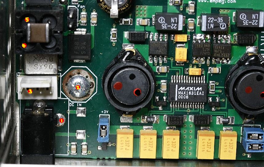 See, the neg contact from the DC-in jack, first passes through that black coil thingie (under contacts #4, #5 and the two just right of those), to suppress any RF transients that might be present. After that, it goes directly to the ground layer of the PCB. So if the jack is now fine, there are only two possible places for the connection to be broken. One is at that black coil thingie, and the other is in the internal PCB traces that connect to it. Worse case, if we cannot find the break, would be to solder a new wire from the jack to the other side of the break, which will fix it completely. Sort of like what you do to see it actually power up right now, except we still would like the coil to be in the circuit. I'm just not sure which two contacts on that black coil thingie are for the ground wire, and which side the jack connects to. Easy enough to figure out with an ohmmeter, but I'm (far) away from my Mk2 empeg right now. So you could probe the four contacts on the coil (including labels #4, #5), to see which two of them are GROUND (the other two serve a similar purpose for the incoming +12V connection)[/i]. One contact should show zero ohms to ground (say, that nearby ground screw, at label #2), and the other should show perhaps 3 ohms to ground. The latter is where the jack should connect. So you should see zero ohms from that one to the NEG on the jack, on a good player that is. In your case, neither should show a connection to anywhere on the jack (or so goes our current debugging theory ). Cheers
Edited by mlord (26/12/2008 13:39)
|
|
Top
|
|
|
|
|
#318678 - 31/01/2009 12:49
Re: not powering up
[Re: mlord]
|
member
Registered: 29/12/2006
Posts: 159
Loc: E.Sussex, UK
|
Hi Mark, apologies for not replying sooner, been a bit hektic round here for a while now! hope ya had a good xmas and new year! right, just in case it makes any difference what-so-ever to the readings, the ohm reading across the multimetre probes is 4 ohm. 4&5 read 4 ohm 1 or 2 to the pin parallel to pin 5 is seemingly ranging from .4 to .750 m ohm, the reading won't fix. think i'm gonna buy a new multi meter, this one (amprobe - rather expensive 8yr ago) seems all over the place, across the robes started at 1ohm, checked it later and it's 4 ohm, then 8ohm. can't work it out! ok, i'm gonna ignore ohms for a moment, using the continuous circuit (audible) feature..... place probe on jacks internal neg contact, circuit only on point 1, as expected, and point 3. using point 2 as start, curcuit on point 4 & 5, chassis also. see diagram for further... i think it's self explanatory, i'm guessing there's a break between pin 2, neg, and the coil or ground screw?  thanks. Hugh
Edited by crazyplums (31/01/2009 12:50)
|
|
Top
|
|
|
|
|
#318683 - 31/01/2009 13:09
Re: not powering up
[Re: crazyplums]
|
carpal tunnel
Registered: 29/08/2000
Posts: 14548
Loc: Canada
|
think i'm gonna buy a new multi meter Perhaps try a fresh battery in the existing unit first..
|
|
Top
|
|
|
|
|
#318684 - 31/01/2009 13:11
Re: not powering up
[Re: mlord]
|
carpal tunnel
Registered: 29/08/2000
Posts: 14548
Loc: Canada
|
Are you sure you are probing all of this stuff WITHOUT ANYTHING PLUGGED INTO THE JACK ??
Because it all keeps coming back to "BAD JACK".
Cheers
|
|
Top
|
|
|
|
|
|


 Previous Topic
 Index
Index