#94688 - 19/05/2002 22:23
 My failed attempt at an S/PDIF output board
|
pooh-bah

Registered: 13/01/2002
Posts: 1649
Loc: Louisiana, USA
|
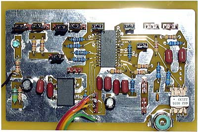
I installed the thing in the RIoCar this afternoon, but the board refuses to work. Voltages seem fine throughout the board, the oscillator is oscillating at 11.2896 MHz like it should, the critical jumpers are set to the proper positions, and the inputs are wired to the RioCar accodring to an earlier post by Hugo. It's being fed +5 volts from the RioCar board off of one of the jumpers. I can't find any shorts or improperly connected components. I only have a six inch lead off of the IIS pads. That shouldn't necessitate a buffer circuit should it? Other than that, the only thing left is to try and concoct some sort of reset circuit, as that pin is currently floating, but I have my doubts that is going to work. I'm not beat yet, but I am feeling very frustrated. On the plus side, the Rio still works.
Anyway, here are some pics so you can at least see what I've been working on.
Pic 1
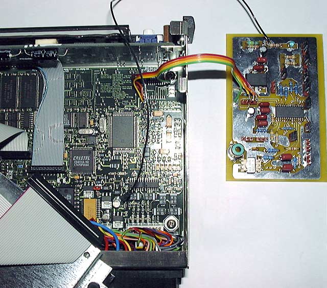
Pic 2
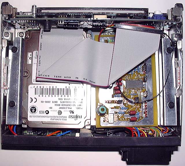
Pic 3
Stu
Edited by maczrool (19/05/2002 22:27)
_________________________
If you want it to break, buy Sony!
|
|
Top
|
|
|
|
#94689 - 19/05/2002 23:08
 Re: My failed attempt at an S/PDIF output board
[Re: maczrool]
Re: My failed attempt at an S/PDIF output board
[Re: maczrool]
|
new poster
Registered: 05/01/2002
Posts: 18
Loc: California
|
I imagine that the reset is probably needed. As a quick test jumper that pin low before power on and high after power on. The eval board has a RC network through a CMOS buffer.
A quick look at the datasheet shows that Cirrus Logic offers a free design review service. Maybe they would be so kind as to help you out and have a look at it. Never hurts to ask I think...
Ryan
|
|
Top
|
|
|
|
|
#94690 - 20/05/2002 00:28
Re: My failed attempt at an S/PDIF output board
[Re: maczrool]
|
pooh-bah
Registered: 12/01/2002
Posts: 2009
Loc: Brisbane, Australia
|
I haven't been following closely, but I remember you mentioned something about floating the reset line - I assumed the datasheet had said this was OK. This would definitely not be recommended unless the datasheet says the device has an internal pullup or internal reset circuitry of it's own. At the very least you should have a resistor pulling up or down dependant on whether reset is active low or high respectively. Even then a simple RC network should probably work OK.
From a fair bit of embedded EMC work, reset lines are also some of the worst culprits when it comes resets induced by external EMC. I would never ever leave one floating.
How different is the design from the eval board? In most cases (definitely not all though) eval boards are fairly well designed and if you copy them you almost always get at least something working.
6 inches isn't real short and I wouldn't want that in practice but for mucking around with a first go board, it should work.
Edit: If you don't mind send me the schematic and I'll have a look for you. Do you have a DSO?
Edited by Shonky (20/05/2002 00:32)
_________________________
Christian
#40104192 120Gb (no longer in my E36 M3, won't fit the E46 M3)
|
|
Top
|
|
|
|
|
#94691 - 20/05/2002 09:07
Re: My failed attempt at an S/PDIF output board
[Re: maczrool]
|
carpal tunnel

Registered: 17/01/2002
Posts: 3996
Loc: Manchester UK
|
Is there something wrong with the server hosting your pics, or has it succumbed to the slash-dot effect? I've tried half-a-dozen times to view them without getting anywhere...
_________________________
Cheers,
Andy M
|
|
Top
|
|
|
|
|
#94692 - 20/05/2002 09:14
Re: My failed attempt at an S/PDIF output board
[Re: andym]
|
carpal tunnel

Registered: 27/06/1999
Posts: 7058
Loc: Pittsburgh, PA
|
Works for me  ...
|
|
Top
|
|
|
|
|
#94693 - 20/05/2002 11:08
Re: My failed attempt at an S/PDIF output board
[Re: andym]
|
pooh-bah
Registered: 13/01/2002
Posts: 1649
Loc: Louisiana, USA
|
I don't know what the deal is. Maybe a DNS issue. Not sure. If it helps, it's my own personal server in the house. All I can say is, it works from this end. I'll post the pictures on the BBS.
Stu
Attachments
93341-spdif_board1.jpg (393 downloads)
Edited by maczrool (20/05/2002 11:12)
_________________________
If you want it to break, buy Sony!
|
|
Top
|
|
|
|
|
#94694 - 20/05/2002 11:09
Re: My failed attempt at an S/PDIF output board
[Re: maczrool]
|
pooh-bah
Registered: 13/01/2002
Posts: 1649
Loc: Louisiana, USA
|
Pic 2
Attachments
93344-rio_and_board.jpg (356 downloads)
_________________________
If you want it to break, buy Sony!
|
|
Top
|
|
|
|
|
#94695 - 20/05/2002 11:11
Re: My failed attempt at an S/PDIF output board
[Re: maczrool]
|
pooh-bah
Registered: 13/01/2002
Posts: 1649
Loc: Louisiana, USA
|
Pic 3
Attachments
93345-rio_and_board_inside.jpg (393 downloads)
_________________________
If you want it to break, buy Sony!
|
|
Top
|
|
|
|
|
#94696 - 20/05/2002 12:37
Re: My failed attempt at an S/PDIF output board
[Re: Speedy]
|
pooh-bah
Registered: 13/01/2002
Posts: 1649
Loc: Louisiana, USA
|
I am going to try a jumper as you suggest. I also thought about turning to the design review service. If nothing else works, I'll try that.
Thanks,
Stu
_________________________
If you want it to break, buy Sony!
|
|
Top
|
|
|
|
|
#94697 - 20/05/2002 13:18
Re: My failed attempt at an S/PDIF output board
[Re: maczrool]
|
carpal tunnel
Registered: 17/01/2002
Posts: 3996
Loc: Manchester UK
|
Just got home and found it works on my cable modem. Damn and blast the BBC and their shoddy internet connection! Thanks for taking the time to resend the piccies! 
_________________________
Cheers,
Andy M
|
|
Top
|
|
|
|
|
#94698 - 21/05/2002 19:50
Re: My failed attempt at an S/PDIF output board
[Re: Shonky]
|
pooh-bah
Registered: 13/01/2002
Posts: 1649
Loc: Louisiana, USA
|
I tried the circuit with a a single pole, double throw switch to both ground and +5 volts with a 47k resistor in line with the +5 volts (as is done in all other cases on the eval board) to the RST pin. It still doesn't want to work, but the interesting thing is that when the RST pin is high, I now get a low level, high pitched digital buzzing noise from my DAC. That may mean I'm getting closer. Any other suggestions? I'll try posting the exact schematic as best I can later. I am going to continue to make adjustments to the jumpers and see if that helps.
Stu
_________________________
If you want it to break, buy Sony!
|
|
Top
|
|
|
|
|
#94699 - 22/05/2002 05:27
Re: My failed attempt at an S/PDIF output board
[Re: maczrool]
|
carpal tunnel
Registered: 19/05/1999
Posts: 3457
Loc: Palo Alto, CA
|
If you send me your cct diagram (in some form I can read: I can read ranger 2 or orcad... or pdf!) then I can check it against the Rio Central cct diagram, which also uses a CS8405 - albeit in software mode. Might be able to help...
Hugo
|
|
Top
|
|
|
|
|
#94700 - 22/05/2002 08:43
Re: My failed attempt at an S/PDIF output board
[Re: maczrool]
|
stranger
Registered: 12/04/2002
Posts: 35
|
I'm pretty sure the clk for this chip must be in phase with the audio clk and it looks like you are using a separate xtal for the job, which won't work. I mentioned this in one of the other chains and Hugo suggested that the 11.2896Mhz could be picked up on the main PCB but he had brought the signal out to a pad.
I also remember that this chip is a bugger to configure as many of the options have interdependencies. If you post your config pin state I'll try and verify against the datasheet. Also what are you 'talking' to, is it an amp, minidisc or PC with digital in. Do you have another device with digital out to make sure those devices are working ok? Have you put a scope on the coax out to see if a carrier signal is present (I'm pretty sure it should be even with no input to the chip)?
Does the receiving device display any messages, it's not complaining about the serial copy protection bit?
|
|
Top
|
|
|
|
|
#94701 - 22/05/2002 10:26
Re: My failed attempt at an S/PDIF output board
[Re: snowwhite]
|
pooh-bah
Registered: 13/01/2002
Posts: 1649
Loc: Louisiana, USA
|
Good point on the oscillator. I just assumed since the onboard (on my board that is) oscillator is 256x the sampling rate that it would work. I was beginning to think along those lines myself. I read the post on the mainboard crystal, but will reread it. I will also try tapping into the Empeg's Xtal.
I will post the pin config later today and also a schematic cludged up from the Crystal PDF. Unfortunately, I don't have a scope that works properly. I have been connecting the output on the board to a "Flying Cow" D/A/D converter. It has a valid data indicator, which never illuminates when the output board is connected to it. It's beginning to sound as if I have bitten off more than I can chew. But I'll keep trying.
Stu
_________________________
If you want it to break, buy Sony!
|
|
Top
|
|
|
|
|
#94702 - 24/05/2002 10:52
Re: My failed attempt at an S/PDIF output board
[Re: altman]
|
pooh-bah
Registered: 13/01/2002
Posts: 1649
Loc: Louisiana, USA
|
Here is a schematic of the S/PDIF board. This is the best I could come up with given the tools I have to work with, but it is an accurate representation of the board as it is currently setup. I was unsure about a lot of the settings on the chip, so if any stick out as incorrect for the consumer S/PDIF format let me know. All jumper settings are indicated by the red elipses.
Thanks for everyone's help.
Stu
Please disregard the schematic attached to this message. It has a minor error on the Pin 1 label which should read "COPY/C" not "CDOUT". Here is a link to the proper schematic.
Edited by maczrool (24/05/2002 13:43)
_________________________
If you want it to break, buy Sony!
|
|
Top
|
|
|
|
|
|

 Previous Topic
 Index
Index