Unoffical empeg BBS

Quick Links: Empeg FAQ | RioCar.Org | Hijack | BigDisk Builder | jEmplode | emphatic
Repairs: Repairs

Topic Options
#275011 - 25/01/2006 21:29 Alternate way of connecting button LED's
Narkotic
member

Registered: 20/02/2002
Posts: 158
Seeking an alternate way of illuminating the button LED's independantly from the hijack logic (not sure how to ask this one).

Since i've extended the display, having the button LED's hooked up will cause intermittant issues with the empeg. Even if I have them disabeled in hijack, they still momentarily blink when the player boots up (sets the brightness of the display) causing the display to go dim. I've tried to remedy this using an initial macro in hijack to set the brightness up after it is booted up. Unfortuantly, when the macro runs, it causes the button LED's to blink each time the brightness is turned up or down a notch. This can intermittantly cause the display to go dim again. It is also intermittant when the button LED's turn on (when the empeg is powering on).

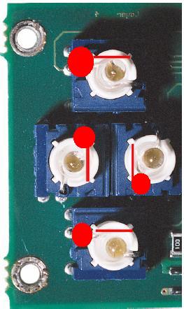
What i'd like to do is just give the LED's power when the player is on, forcing them to always be on at 100%. After looking through the install manual from eutronix, it seems that they need 5vDC. Is there a way of doing this w/out desoldering the button LEDS from the board? With the knob board, I could probably just disconnect the signal lead and ground it i'm assuming, however the ground leads to the button LED's appear to be directly connected to a regulated ground?

I've tried everything from timing the macro to changing the buttonled_off options in hijack. I've also tried 10nf-20nf capasitors on the dimming logic behind the display board with no luck.

Thanks alot!!

Top
#275012 - 25/01/2006 21:50 Re: Alternate way of connecting button LED's [Re: Narkotic]
tfabris
carpal tunnel

Registered: 20/12/1999
Posts: 31565
Loc: Seattle, WA
You know, I had issues with my buttons recently, and the solution was to fix the (very hard to detect) broken solder joint on pin 1 of the PIC near the buttons. Your problem wouldn't be as simple as that, would it?
_________________________
Tony Fabris

Top
#275013 - 25/01/2006 22:28 Re: Alternate way of connecting button LED's [Re: tfabris]
Narkotic
member

Registered: 20/02/2002
Posts: 158
I've read that thread and probably just about every other thread pertaining to these sorts of issues... I'm done with trying to fix it, it is simply something to do w/ the extra 7" of display ribbon that I have. When the extender is out of the loop, everything works fine. I don't mind losing the dimming functionality of the LED's...

Top
#275014 - 25/01/2006 23:16 Re: Alternate way of connecting button LED's [Re: Narkotic]
Narkotic
member

Registered: 20/02/2002
Posts: 158
Look at the attachment, I drew red circles over the "signal" lines. could I just lift those and ground them? That would turn them on as soon as the display receives power right?


Attachments
275165-buttons.JPG (173 downloads)


Top
#275015 - 26/01/2006 06:30 Re: Alternate way of connecting button LED's [Re: Narkotic]
StigOE
addict

Registered: 27/10/2002
Posts: 568
You could take off the resistorpack, solder some wires to the pads going to the leds (or directly to the pads going to the resistorpack), solder a resistor to each wire (same value as the resistorpack), tie the other end of the resistors together and solder on another wire and connect this wire to either 5V or GND depending of which side of the leds this whole thing is connected to.

Stig

Top
#275016 - 26/01/2006 10:34 Re: Alternate way of connecting button LED's [Re: Narkotic]
schofiel
carpal tunnel

Registered: 25/06/1999
Posts: 2993
Loc: Wareham, Dorset, UK
The flash of the LEDs when the level is set is a consequence of the original design. It happens. As for a level change causing the VFD level to change and stay dim, it sounds like the level setting data stream coming back to the dimmer are either being corrupted, or you are suffering from an extended version of the original "dimmer glitch" problem, probably exacerbated by the extention. Look at what the AS4800 dimmer chip does/receives for clues as to what is happening.
_________________________
One of the few remaining Mk1 owners... #00015

Top
#275017 - 26/01/2006 14:56 Re: Alternate way of connecting button LED's [Re: schofiel]
Narkotic
member

Registered: 20/02/2002
Posts: 158
Although your prognosis makes perfect sense, I don't have the equipment or time to mess around with this anymore. I'd like to just wire the LED's to come on when the player comes on...

Top
#275018 - 26/01/2006 15:01 Re: Alternate way of connecting button LED's [Re: StigOE]
Narkotic
member

Registered: 20/02/2002
Posts: 158
Sounds like to much work, I believe the resistor is connected to the anode of the LED. The cathode is connected to a pad on the board which is "signal" or a regulated ground to control the dimmer. Could I just lift the left pin where signal is connected (for the knob board) and just ground it?


Top
#275019 - 26/01/2006 16:36 Re: Alternate way of connecting button LED's [Re: Narkotic]
StigOE
addict

Registered: 27/10/2002
Posts: 568
Oh, I thought it was the resistorside that was controlled, not the other side of the leds (didn't have a displayboard at hand), so my suggestion wouldn't work... Yeah, should be possible to just ground the signalwire going to the knobboard. This time I did check a knobboard...

Stig

Top
#275020 - 26/01/2006 16:39 Re: Alternate way of connecting button LED's [Re: StigOE]
Narkotic
member

Registered: 20/02/2002
Posts: 158
Ah, thanks... Could I just lift the pin that the signal wire is connected on on the LED and ground that? That would then light up the one LED and the knob board at power up correct?

Top
#275021 - 26/01/2006 18:03 Re: Alternate way of connecting button LED's [Re: Narkotic]
StigOE
addict

Registered: 27/10/2002
Posts: 568
Well, I was going to suggest that the easiest thing to do, albeit a bit drastic, would be to cut the track going to the topmost pin marked red in your picture (same as the signalwire going to the knobboard is connected to) and ground it, but I checked on a displayboard and the other 3 leds are connected together with a track which goes to a via coming up under a chip. I don't know if this is the PIC controlling the buttons (didn't want to bend open the vfd to look), would possibly have to cut this track too... So it's probably best to let Schofiel tell us what the best thing would be, which probably would be "Leave it alone"...

Stig

Top
#275022 - 26/01/2006 18:23 Re: Alternate way of connecting button LED's [Re: Narkotic]
Narkotic
member

Registered: 20/02/2002
Posts: 158
Well, I got impatient. It worked by just grounding each cathode of the button LED's and the signal wire for the knob board. Problem solved.

Top