OK - makes sense.

Get the DTDP switch I suggested.
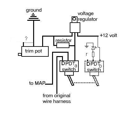
Run the wiring in your original diagram to one set of contacts and then wire the LED on the other set. Hook the LED up to the center and same side pin as the input from the voltage regulator is on the other set. r=1kOhm is probably good for most normal LEDs (non-highintensity or low-power)

As to connecting the unused pin on the pot to the grounded pin depends on what happens worstcase if the slider disconnects from the resistive path. Is it worse if there's no connection to ground or worse if there's a high resistance path? Probably depends on what the voltage regulator does if you disconnect ground - I don't know but guess you'd get 0V out. If you did the extra connection you will get a higher than wanted voltage (don't feel like looking up the LM317 spec sheet and calculate just how high the voltage would go, but probably 12+ V)
Edit:
Looked at the original site you linked.
Voltage out is Vout = 1.25V*(1+R1/R2) where R1 is 220 Ohm
and R2 0-1000 Ohm.
If you included the extra connection, the failure of the slider to connect would give 1.25*(1+220/1000) which is 1.525V.
Leaving it out would probably lead to 0V out. Compared to the nominal 5V the original circuit had, both might be effectively just as bad... but that's just speculation.
/Michael

 Previous Topic
 Index
Index
