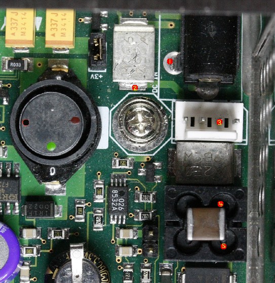
Here is another photo of the area under scrutiny. I have labelled some of the key test points, to ease discussion of exactly where to probe etc..
1. The outside (negative) contact of the DC power jack.
2. The 2.5A GND fuse contact (the top surface is the other contact).
3. The NEG(-) contact for the black wire (unplugged) from the docking connector.
4. A small coil that connects the fuse to the empeg ground plane -- the contact is deep inside the hole here.
5. The other contact of the small coil (I don't know which contact is which).
What you should do, is measure ohms between all combinations of those red dots, plus across the two contacts of the fuse itself, and post your complete findings here.
The ground circuit actually goes from points 1 and 3, through the fuse at point 2, and then through the coil (points 4,5), after which it finally connects to ground/chassis of the rest of the empeg.
There is a nearly identical lead-in circuit for the POS(+) side of the power, with a second fuse and a second half of the coil for that. But that stuff appears to be working in your player, so ignore it.
Cheers
Attachments
 Description: The +12V PSU front end of a Mk2a RioCar.
Edited by mlord (01/12/2008 15:34)

