What does your ohm-meter show across the two contacts just right of contact numbers 4 and 5 in this photo? That is, the two very similar but unlabelled contacts on the same black thingie.
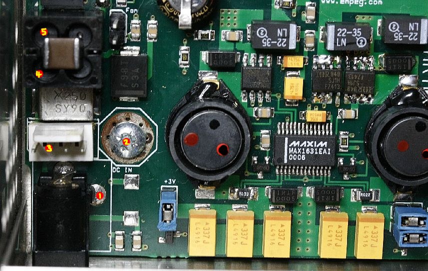
See, the neg contact from the DC-in jack, first passes through that black coil thingie (under contacts #4, #5 and the two just right of those), to suppress any RF transients that might be present. After that, it goes directly to the ground layer of the PCB.
So if the jack is now fine, there are only two possible places for the connection to be broken. One is at that black coil thingie, and the other is in the internal PCB traces that connect to it.
Worse case, if we cannot find the break, would be to solder a new wire from the jack to the other side of the break, which will fix it completely. Sort of like what you do to see it actually power up right now, except we still would like the coil to be in the circuit.
I'm just not sure which two contacts on that black coil thingie are for the ground wire, and which side the jack connects to. Easy enough to figure out with an ohmmeter, but I'm (far) away from my Mk2 empeg right now.
So you could probe the four contacts on the coil (including labels #4, #5), to see which two of them are GROUND (the other two serve a similar purpose for the incoming +12V connection)[/i].
One contact should show zero ohms to ground (say, that nearby ground screw, at label #2), and the other should show perhaps 3 ohms to ground. The latter is where the jack should connect. So you should see zero ohms from that one to the NEG on the jack, on a good player that is.
In your case, neither should show a connection to anywhere on the jack (or so goes our current debugging theory

).
Cheers


 Previous Topic
 Index
Index
