I think the best place to connect external 3.3V power to the BT-dev board would be at the (white, 2-pin) battery connector (or to the "Battery Current" jumper).
That input will accept up to 4.4V, and it gets internally regulated to what the various parts of the dev board want.
Connecting it directly to the 3.3V (OUTPUT) on the top-left header isn't ideal, and could be why parts of the board want to overheat.
Now, why the external USB power wasn't working: this should just be due to the 5V-to-3.3V conversion chips perhaps having failed.
There are two chips in series for this: U14, and then U1 (labelled photo attached).
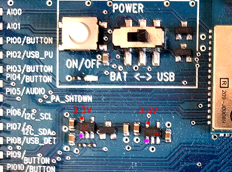
U14 (on the right) converts the 5V from USB down to 3.6V ("battery level").
U1 (on the left) converts the 3.6V from U14 down to 3.3V ("logic level").
You can check for correct operation of each of those with a voltmeter.
Power the board from the USB connector (or possibly the UART connector, but I'm using the USB connector here).
The top left pin of each chip is its output.
Measure voltages using either of the USB shells as GND.
The chip on the left (U1) should be outputting 3.3V,
and the chip on the right (U14) should show 3.6V.
If either chip doesn't show the correct output, then check the input to each chip, on the bottom left pin (
magenta dots in the photo).
So, check those and report back.


 Previous Topic
 Index
Index
